Monday, October 6, 2025

New Feed Lines for 23cm EME


New feed lines were going to be required for my 23cm EME station.  For transmit I needed something that could handle as much as 700-watts on 23cm.  For several years I have depended on coaxial cable which is built in Italy by Messi & Paoloni.   They have been producing cables since 1984 and have received very good reviews.  I have made multiple purchases from M&P and have always been amazed at the quality of their cable and connectors.  For my transmit cables I decided on their HYPERFLEX 13 /.500" which is rated to handle 786 watts on 1296 MHz.  For my receive cable I chose their ULTRAFLEX 10 /.400" which is a little smaller and lighter.  I ordered a 6.5 m section of each cable with Solder type "N" connectors installed on BOTH ends.  I also ordered a 1.1 m piece of the larger cable as a jumper from the amp to the wattmeter.

The center conductor of the HYPERFLEX 13 contains 37 wires!  That makes it a very flexible cable. Click Here for a video showing how they install a soldered (or solderless) "N" Connector.  Their connectors are designed specifically for their cables.

I placed my order by email in the evening on September 29th, well after M&P had closed for the day.  In the morning of October 1st (1-1/2 days later) I had a response where they told me the HYPERFLEX cable with the black jacket was out of stock but they could supply their HYPERFLEX 13 Sahara with a white jacket.  Both cables have the same specifications but the Sahara cable has a white jacket to help reduce the attenuation degrading which a black cable can experience as the ambient temperature increases.  I quickly agreed to have the white jacketed cable substituted in my order for the HYPERFLEX 13 cables.  Just after midnight (my time) on October 2nd, I received the order confirmation and a PayPal link for me to make the payment.

Unbelievably the cables arrived at my QTH in the afternoon of October 6th.  Just 7 days after I placed the order!  WOOF!  Can you believe three custom-built coaxes with Soldered "N" connectors installed, were produced and DELIVERED from Italy in just 6 days?  Well, in my experience, this is NOT unusual!  My previous orders have taken only 6 or even 5 days to have connectors installed on custom lengths of cable and shipped from Italy to West Virginia.  

Click on the photo of the cables on the right for a larger view.  You can easily see the quality of the Soldered "N" connectors.  I continue to be very happy with the cables and connectors I purchase from M&P.  And I do not hesitate to recommend them.

Sunday, September 28, 2025

3D Printed Case for Amplifier Current Meter

    In order to monitor the current being pulled by the AG6EE 23cm Amplifier, I purchased a Bayite DC 6.5-100V 0-100A LCD Display Digital Current Voltage Power Energy Meter Multi-meter Ammeter Voltmeter with 100A Current Shunt for $17.99 from Amazon.  That looked like a near perfect solution.  However, I did not want to just have that small (3.5"x2"x1") meter just lying around on the shelf or the top of the amp.  So, I searched for a box that I could mount that meter into and by chance came upon EXACTLY what I wanted as a 3D Print called "Power Monitor case V2" on Thingverse. Now the problem became "How Do I Print This?" since I do not own a 3D Printer.  Again, Mr. Google let me know that the Kanawha County Public Library has an area called the IDEA Lab where they will print 3D Digital Models and only charge for the filament used.  WOW!  
 
    I checked into the process and found I needed to take a Tutorial and a short Quiz, then sign a waiver to use this service.  That took only a short time and acquainted me with the 3D printing process.  I copied the necessary files from Thingverse to a USB Thumb Drive and took it and my completion certificate from the Tutorial plus the waiver to the library.  They said it should take 2 hours to print it and I could come back the next day to pick it up.  I did and they charged me $1.40 for the filament that was used.  Amazing!
 
    The case was printed in 2 pieces (back and front cover) see image on the right of the completed 3D print (click on any image to see it larger).  Once I had it home, a half hour of trimming off any excess plastic gave me the parts I needed to mount the meter.  A trip to the hardware for some 3mm hardware to mount the front cover and I was in business. 

    Once I had the case cleaned up and the necessary mounting hardware, I needed to wire the meter shunt to the power supply and connect the the four wires from the Current Meter to the shunt and the positive terminal of the Mean Well power supply. 

    As you can see in the final photo, the meter is now mounted in the 3D printed case and is ready to by used in my 23cm EME system to monitor the 48VDC power supply and the current being supplied to the AG6EE Power Amplifier.  The photo at the top of this page shows the meter with the backlight on but it was difficult for me to get a usable photo with the backlight on.

Saturday, September 6, 2025

Adding a Leo Bodnar GPSDO to the IC-9700

GPSDO Injection Board Installed

Since the Icom IC-9700 can experience significant frequency drift, especially on 23cm, and this drift can affect digital modes -- I decided to add a GPS Disciplined Oscillator (GPSDO) to the radio.  Leo Bodnar offers such a device which connects to the radio's "REF IN" connector and supplies an external 49.152 MHz signal (derived from GPS satellites) to lock the transceiver's internal frequency reference to a stable signal.  This will insure the radio will stay within 1 Hz on all bands.

The product I purchased is the High Stability Kit for ICOM-9700 from Leo Bodnar.  This comes with the LBE-1420 GPSDO locked clock source which is a GPS receiver, an antenna for that receiver, an injection board for the IC-9700, and appropriate cables.  In the photo on the left (click for a larger image) you can see the injection board "1" installed (and outlined in yellow), the SMA connector for the GPS receiver "2" placed in the "REF IN 10MHz" location, and the original SMA connector "3" which was removed and taped to the inside of the radio.

The Leo Bodnar website has instructions for opening the radio and installing the injection board.  It is important to use the proper screwdriver, a Japanese Industrial Standard (JIS)  #2 and not a Phillips screwdriver to remove the 12 screws from the radio.  My only boo-boo was that I removed the 12 screws from the TOP of the case and not the BOTTOMDUH!  I wasted 15 minutes doing that.  Otherwise, it took me 1-1/2 hours to locate the tools needed, perform the install, and return the tools to the garage.  I was helped a bit by a video on YouTube describing the install and the setup of the device and the radio and also this YouTube video.

I did not have a frequency generator to produce a tone for fine tuning of the "REF Adjust" menu item in the IC-9700.  I did find a birdie and made some minor adjustments using that.  However, once I can source a relatively accurate signal source, I will do that part of the setup again.

This part of my 23cm EME project was pretty simple and took very little time.  Hopefully this will insure that my radio is on frequency and not drift.  This should allow me to make a few more EME contacts or make them more quickly. 

Thursday, August 7, 2025

Theodolite Application for Locating the Moon

Theodolite is a multi-functional app that combines a compass, inclinometer, rangefinder, GPS, map, and camera with geo-overlay for augmented reality. It's essentially a digital theodolite, allowing users to measure angles, distances, and positions using their smartphone or tablet.  This is the perfect way to locate the moon in azimuth and elevation for pointing the antenna.  I purchased this app from the Apple Store for $9.53 and in my opinion it is well worth that price.

Below is my first attempt at using this app to locate the moon.  Local time was just after midnight and Full Moon is in 2 days so this moon was over 90% illuminated - it is bright!  You can see a tree to the left of the moon and also a portion of the edge of my garage.  This image was taken at the point where I plan to set up my Sub-Lunar Folding Dish.  At the time I took this photo the declination was -27° so the moon was not very high in the sky even though it was nearly due South of me.  You can see that the Horizon Angle on the left shows the phone was tilted 2.7° away from horizontal.  (Click on any image to see a larger version.)

I placed inside the Theodolite image a Yellow bordered box showing the Astronomical Data from WSJT-X for the same date/time.  You can see the app shows an Azimuth of 187° and WSJT-X shows 187.5° and since the moon is actually below the crosshairs, the indicated Elevation Angle on the right (of +25.3°) was a little off from the WSJT-X number of 23.7°  At the top of the screen the app also shows my latitude/longitude and elevation. 

I learned that I might want to set my iPhone on a tripod to keep it steady in the future.  Just holding the phone in my hands it was difficult to center the moon in the app.  Also, you can push the "Zero" button in the bottom left and it will put a box around the crosshairs in the center of the image.  This box changes color from Red to Yellow to Green then White as you get the image lined up with the horizon so the elevation numbers are correct.  What this button does is to zero all angles at a given orientation of the device, thereby showing angles relative to that reference until you tap the button again.  Once you tap zero again the true angles will be displayed and if the phone has not moved, the Elevation Angle will be correct (as long as the moon is centered in the crosshairs!) 

In the example below the Elevation Angle on the right shows -08.9° but the Horizon Angle on the left shows the image is -01.1° from being level.  And, the yellow box shows you are close to being lined up.  If you line up the image and "then" press the Zero button, it will adapt the image so that the Horizon angle is 0.0°


I don't think this app will take much effort to be able to dial in the location of the moon.  Once I have those numbers, I can set up my SL-1 Az-El Positioner to the current moon location and "hopefully" it will then track the moon automatically.  If I don't have visible moon, I "think" I can still use this app to align it with the dish feed and use that as the starting position for the Az-El Positioner.  The Theodolite User Manual is located HERE.

New EME Challenge - 23cm

After having completed EME QSO's on 6-M, 2-M, and 70cm, I felt it was time to explore a new EME band - 23cm (also known as 1296 MHz.)  Over the past few years there have been huge improvements in equipment for this band and it is possible to purchase all needed items off-the-shelf without the need to "home-brew" any of the needed equipment.  I had delayed moving to this band for several years because my location was not suitable for a parabolic dish antenna (mounted on the ground) to see the moon in the part of the sky which favors Europe.  Too many trees!  However, Paul Andrews, W2HRO, has developed and is marketing a lightweight, folding parabolic dish which uses space-age RF reflective fabric.  His company, Sub-Lunar, sells folding dishes in several sizes, patch feeds, OK1DFC Septum feeds, WinTrack Software/Hardware from N8CQ, Az-El positioners, and many other products to support EME operation.  This "portable" dish concept allowed me to consider other locations on my lot where I could "temporarily" install the antenna with a better view of the moon.
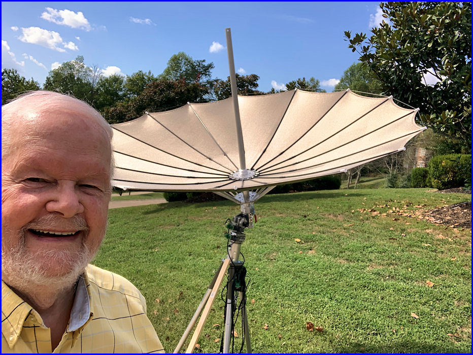
I decided to go with a 1.8M dish (just under 6-feet in diameter) because it was lighter and easier to install and remove.  The 2.4M dish would add about 2 dB to TX and RX signals but I was concerned that I might not be able to handle that larger antenna by myself.  The antenna folds and unfolds like an umbrella!  But it is not weather proof in any of its components and is sensitive to wet and wind!  For that reason, it is a "temporary" antenna.  I plan to only use it when the weather and moon conditions are favorable. UPDATE 2025-08-20 - After talking to several EME'ers and checking with W2HRO at Sub-Lunar, I opted to change my folding dish order to a 2.4M version.  Paul (W2HRO) said he felt I would have no problems with the larger dish.  The earlier models were a little tight but no more.  Bigger is better they say!

Considering this would be a "temporary" set-up, I decided to purchase a rolling cart that could hold all the equipment (power supplies, amplifier, laptop, etc.) and thus it would be extremely simple to just roll the cart out of the garage, erect the antenna, connect the feedlines, and be on the air.

A recent improvement in folding dish setups is the OK1DFC Lightweight Septum Feed.  Originally those stations with a folding dish used a "Patch Feed."  But on 23cm (1296 MHz) EME signals use circular polarization.  In order to get circular polarization from a patch feed, you need to incorporate a 90° hybrid to provide circular polarization. However, to switch between LHCP (Left-Hand Circular Polarization) and RHCP (Right-Hand Circular Polarization), a power relay and a set of cables are also required.  A key advantage of the septum feed is its ability to generate both RHCP and LHCP simultaneously!  This eliminates the need for a 90° hybrid.  Also many hybrids are not exactly 90° so that results is less than optimal operation.  And, 90° hybrids are limited in the amount of power they can handle - often only in the 200-watt range. 

Other major components include a preamplifier and a high power amplifier.  Thankfully AG6EE has been building both.  His pre-amp has about 30 dB of gain, with a built-in relay and dummy load - and can connect directly to septum feed.  His 23cm amplifier is spec'd for 600W out (max 700W) and splits the input into TX and RX lines, the RX line has sequenced DC voltage to feed the preamplifier through the coaxial cable.  I have ordered the pre-amp and amplifier from AG6EE and am anxiously awaiting delivery!

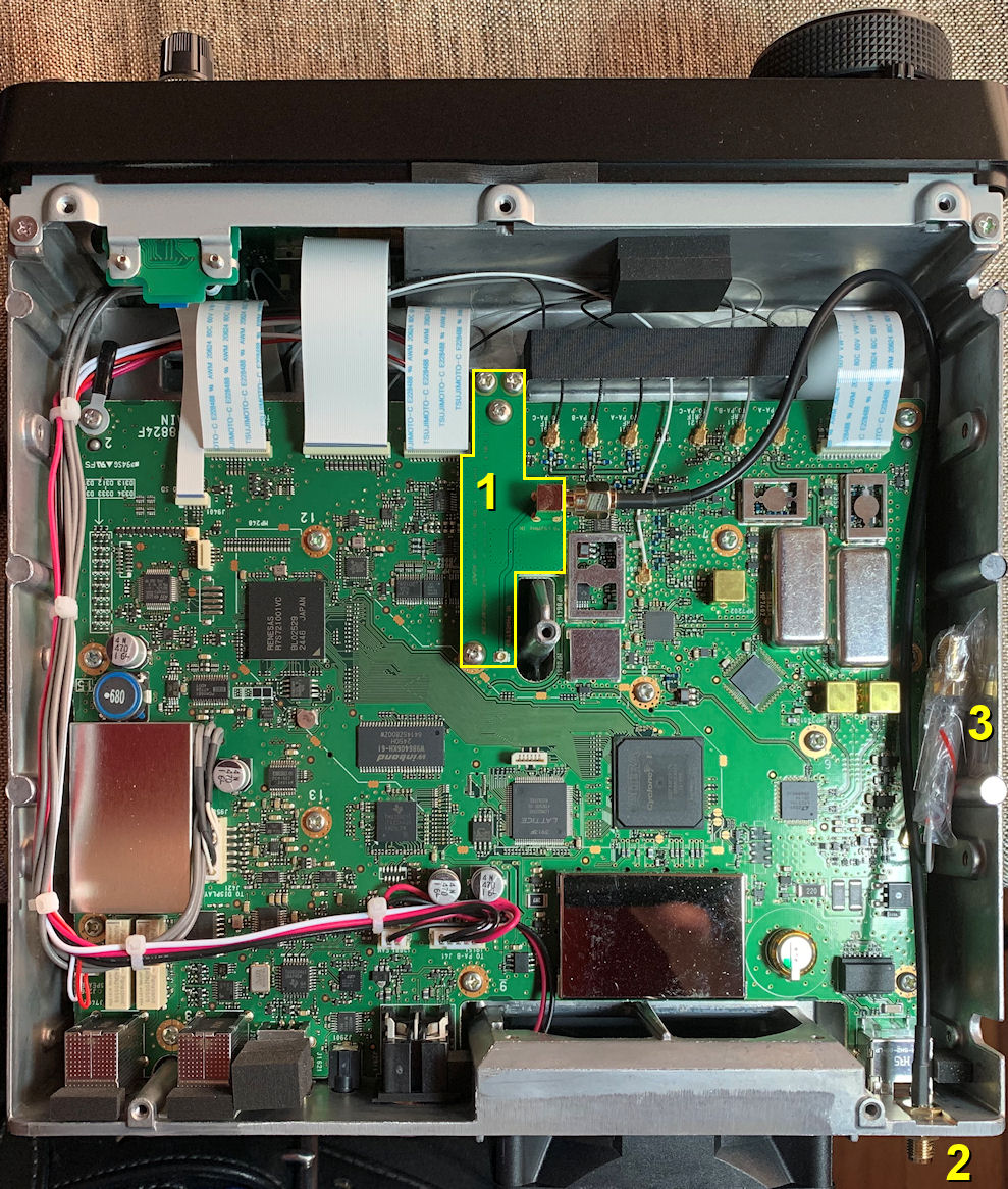
Since I have not operated on 23cm for 24 years (and all that equipment is gone) I needed to acquire a transceiver to operate on 23cm.  I chose the Icom IC-9700.  There is a know frequency drift problem with that radio on 23cm so I ordered a GPSDO from Leo Bodnar to incorporate inside the IC-9700 with an external GPS antenna included. In order to install the Leo Bodnar injection board inside the IC-9700, it is necessary to open the case of the radio.  That requires a special screwdriver. A P2x100 #2 JIS Cross Point Impact Screwdriver is what I ordered from Amazon. And, a laptop would also be required so I purchased a refurbished Dell 5500 Win10 from Amazon utilizing an 8th Generation Intel Core i7 with a 512GB SSD Hard Drive and 32GB DDR4 RAM.  To power the radio and the pre-amp I bought a PowerWerx 30A 14.1 VDC Power Supply, and to power the amplifier, I purchased a Mean Well RSP-2000-48 VDC Power Supply from DigiKey.

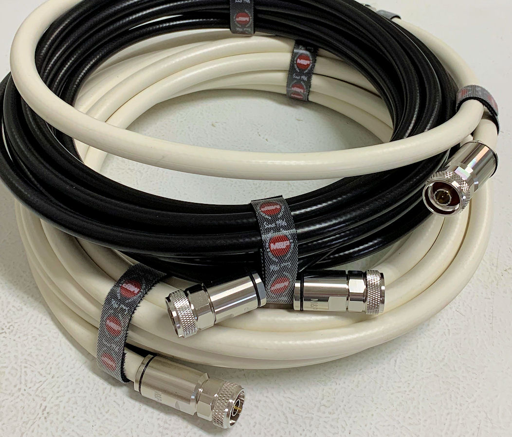
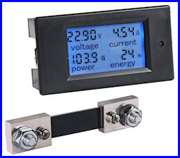
Several other minor items were also purchased - a 23cm 1kW element for my Bird 43 wattmeter, a 50-foot 12/3 extension cord, an AC power strip, a spiral ground anchor to hold the dish tripod down, an LED keyboard lamp, a Shielded/Filtered USB Cable for the IC-9700, and so on.  Then a fair amount of time was spent downloading and installing multiple pieces of software on the computer.  I work on this project every day with the goal of being operational on 23cm EME in time for the ARRL EME Contest on October 11/12.  Fingers crossed!