Showing posts with label Inclinometer. Show all posts

Thursday, August 7, 2025

Theodolite Application for Locating the Moon

Theodolite is a multi-functional app that combines a compass, inclinometer, rangefinder, GPS, map, and camera with geo-overlay for augmented reality. It's essentially a digital theodolite, allowing users to measure angles, distances, and positions using their smartphone or tablet.  This is the perfect way to locate the moon in azimuth and elevation for pointing the antenna.  I purchased this app from the Apple Store for $9.53 and in my opinion it is well worth that price.

Below is my first attempt at using this app to locate the moon.  Local time was just after midnight and Full Moon is in 2 days so this moon was over 90% illuminated - it is bright!  You can see a tree to the left of the moon and also a portion of the edge of my garage.  This image was taken at the point where I plan to set up my Sub-Lunar Folding Dish.  At the time I took this photo the declination was -27° so the moon was not very high in the sky even though it was nearly due South of me.  You can see that the Horizon Angle on the left shows the phone was tilted 2.7° away from horizontal.  (Click on any image to see a larger version.)

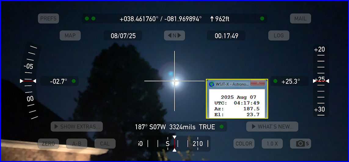
I placed inside the Theodolite image a Yellow bordered box showing the Astronomical Data from WSJT-X for the same date/time.  You can see the app shows an Azimuth of 187° and WSJT-X shows 187.5° and since the moon is actually below the crosshairs, the indicated Elevation Angle on the right (of +25.3°) was a little off from the WSJT-X number of 23.7°  At the top of the screen the app also shows my latitude/longitude and elevation. 

I learned that I might want to set my iPhone on a tripod to keep it steady in the future.  Just holding the phone in my hands it was difficult to center the moon in the app.  Also, you can push the "Zero" button in the bottom left and it will put a box around the crosshairs in the center of the image.  This box changes color from Red to Yellow to Green then White as you get the image lined up with the horizon so the elevation numbers are correct.  What this button does is to zero all angles at a given orientation of the device, thereby showing angles relative to that reference until you tap the button again.  Once you tap zero again the true angles will be displayed and if the phone has not moved, the Elevation Angle will be correct (as long as the moon is centered in the crosshairs!) 

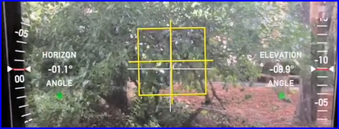
In the example below the Elevation Angle on the right shows -08.9° but the Horizon Angle on the left shows the image is -01.1° from being level.  And, the yellow box shows you are close to being lined up.  If you line up the image and "then" press the Zero button, it will adapt the image so that the Horizon angle is 0.0°


I don't think this app will take much effort to be able to dial in the location of the moon.  Once I have those numbers, I can set up my SL-1 Az-El Positioner to the current moon location and "hopefully" it will then track the moon automatically.  If I don't have visible moon, I "think" I can still use this app to align it with the dish feed and use that as the starting position for the Az-El Positioner.  The Theodolite User Manual is located HERE.

Thursday, October 5, 2017

Finishing the LNA and T/R Relay Box

On Wednesday I tackled some odds and ends of this project.  More epoxy was mixed and applied to the holes in the PVC box to house the LNA and T/R Relay.  The box was free to me but had some 10 1/2-inch holes with cable feedthroughs attached.  I did not need all those holes so I plugged them with epoxy.  That was a learning experience as with the first 4 holes I tried to just put the epoxy in the hole and expected it to stay.  But gravity would pull the epoxy down and open up the hole.  For an hour and a half I kept rotating the box around and around hoping the stuff would set up but it didn't!  At that point I had Evelyn cover a 3x5 card with plastic wrap and I placed that over the 4 holes on the inside of the PVC box.  I then found a cardboard box that would fit inside and apply pressure to the plastic wrapped card.  That worked like a charm.  The next morning the plastic wrap pulled right off and the holes were filled.  Learning how to do that made filling the rest of the holes a snap.

My Step Drill Bit arrived on Wednesday but I had just epoxied the barrier strip to the side of the PVC box so I needed to let that set up before drilling the three 7/8-inch holes for the N-connectors.  A couple of trips to Home Depot were required to obtain some small hardware for mounting the T/R Relay and for the driven element connections on the antennas.  I decided to go ahead and weatherproof the cables going from the antennas to the 2-way power splitter by wrapping them with Scotch 88 electrical tape.  InnovAntennas had already prepared those cables for me with the appropriate connection tab at the antenna end along with Ferrite cores in water-sealed heatsink and N-type male connectors on the other end.  Still, I used the Scotch 88 tape to seal everything as water is a major problem with coax.  At this time I determined which terminal was connected to the center-pin of the N-connector and marked it with red tape.  Both antennas had that terminal connected to the same side of the driven element to assure the antennas would be in-phase with each other.

I then manufactured a mount for the inclinometer from a piece of aluminum angle and a DX Engineering 2-inch clamp.  I knew I could rotate the clamp around the cross-boom to adjust the inclinometer to the correct reading but when I drilled the aluminum angle part for mounting the inclinometer, I elongated one hole.  This would allow me a way to "fine tune" the adjustment.  It was well after dark when I had this ready to mount to the antenna so I asked my wife, Evelyn, to help by reading out to me the elevation angle from the EA4TX ARS USB controller while I made the appropriate adjustment to the inclinometer mount while up on a ladder.  That worked great!  However, when I rotated the antenna and checked the elevation with a digital level, the reading on the ARS USB box did not agree.  Looks like I need to calibrate the inclinometer.

Using the Step Drill Bit it was a SNAP to enlarge the one hole and drill two others large enough to pass a cable with an N-connector attached through the PVC box.  Having the right tool makes a huge difference in any job.  This is probably not the best tool for this job but it worked great for me!  Once I was able to pass a cable through the side of the box (simulating the cable that would come from the power divider) it was easy to position the T/R relay and drill a couple of mounting holes for in in the metal plate that was already attached to the bottom of the PVC box.  The LNA would just be supported by the connectors so no mounting was needed there.  With the T/R Relay mounted, I now moved on to wiring the relay and LNA to the barrier strip.

I made sure to put a diode across the coil of the T/R Relay.  This is done because an inductor (the relay coil) cannot change it's current instantly so the flyback diode provides a path for the current when the coil is switched off. Otherwise, a voltage spike will occur that may cause arcing on switch contacts or possibly destroy switching transistors.

The T/R relay I am using (Relcom RDL-SR012) has a set of contacts that will indicate when the relay has switched.  There are three contacts: C-Common, NO-Normally Open, and NC-Normally Closed.  I wired those to the Barrier Strip and a shielded cable brings them down to the shack.

 12 VDC connections for the LNA and 24 VDC connections for the T/R Relay were also wired to the barrier strip.  They will be connected over separate shielded cables to the appropriate voltage sources in the shack.  In the photo on the right you can see everything hooked up.  Three shielded cables exit the box through one of the feedthroughs that came with the box and they are color coded (to try and prevent me from making more mistakes!)  The LNA is at the bottom (mounted on a slight angle to allow for easier cable entry into the box.  The T/R Relay is on the bottom and the Barrier Strip on the right.  You can see markings on the inside of the box above the Barrier Strip to note what gets hook to what screw.  The LNA is connected to the Normally Open contact on the T/R Relay with a right-angle N-connector.  This just keeps the loss to a minimum and makes the box less crowded than if I had used a cable.  All the spade lugs are crimped AND soldered.  Why?  Because I'm excessively fussy (some would say "anal!") You can click on any photo to see a larger image.

The last few things I did before calling it a day was to install a clamp to hold the 7/8-inch Heliax (TX feedline) to the Hazer cage.  Then I put the cover on the LNA and T/R Relay box and weather-proofed the holes around the cables.  Finally, I rotated the antennas to exactly vertical (90.0° on the SmartLevel) in order to calibrate the inclinometer.  Much to my surprise, the EA4TX ARS USB controller says the array is pointed at 94° so that was nice.  I may not have to do much to finish the calibration of the inclinometer.

I woke up this morning at 4:00 a.m., checked the beautiful moon, but then could not get back to sleep - I was too excited and my mind would not stop thinking about this project.  Right now my battery has pretty much run down and I'll be crashing soon.  Should have no trouble sleeping tonight!

Monday, May 1, 2017

Final Mods to the EA4TX ARS-USB Controller

Final Mods to EA4TX Box
If you read my previous post about Modifying the EA4TX ARS-USB Rotor Controller you will have seen where I added a connector to the controller box so that I could connect some remote switches for adjusting the rotors while standing at the base of the tower.  In doing that I had acquired FIVE SETS of Aviation Plugs (Male and Female) which have 6-conductors each for a very reasonable price.  I used one set for the Remote Switches.  But, while modifying the Elevation Rotor control box (so it could be controlled by the EA4TX ARS-USB), I decided to go ahead and use another set of those connectors to allow me to easily set up or move the components of the station.  I removed the grommet which was already installed for the J2 cables and quickly placed one of the 6-conductor jacks in its place.  (It fit perfectly!) I also drilled and punched another hole for one more jack that will be used to interconnect the inclinometer cable.

My EA4TX ARS-USB was purchased with a cable to connect to the Yaesu G800-DXA azimuth rotor.  That cable came already installed by EA4TX and it is the white cable that exits the controller at the J1 hole which you can see at the bottom of the image to the left. (Click on any image to see it larger.)

The red/white/green wires at the top right of the circuit board go to the Elevation Rotor control box.  The red wire brings the 29 VDC from the elevation rotor controller and the white and green wires allow the relays in the EA4TX unit to connect that voltage to the UP and DOWN circuits for controlling the elevation rotor.  The blue/yellow wires at the bottom right go to the inclinometer and provide feedback from it for the elevation angle of the antennas.

Oops!  In later testing of the unit, I found that I could only control the Elevation Rotor to move DOWN by pressing the front panel button on the ARS-USB unit.  The UP button did nothing.  In checking out the reason for that, I found I had forgotten to install a jumper between Pins J2-3 and J2-6 on the ARS-USB board.  I only had the red wire connected to J2-6 which supplied the 29 VDC just to the DOWN point in the Elevation Controller.  Once I connected that jumper, I was able to control both UP and DOWN directions from the ARS-USB unit.

Inclinometer
Also today I wired the inclinometer to the cable which runs out to the tower and wired the plug to the other end to connect to the EA4TX unit.  Then I powered on the EA4TX ARS-USB unit for the first time and checked out the inclinometer.  It WORKS!  I can move the inclinometer and watch the Elevation reading on the EA4TX smoothly change.  Now I need to fabricate a small bracket to mount it to the fiberglass cross-boom.

I chose to go with the inclinometer because I felt my old elevation rotor might not have a good potentiometer for read-back of the elevation angle.  And, it was possible that I might have to use a satellite (TVRO) jack screw for my elevation system and would need the inclinometer for that.  You can see an image of the inclinometer on the right.

Finally, I connected the Yaesu G800-DXA azimuth rotor to the EA4TX ARS-USB controller.  The feedback of the rotor position worked correctly and when I rotated the Yaesu, the azimuth position could be seen changing on the EA4TX unit.  I was also able to push the buttons on the front of the EA4TX controller and cause the Yaesu to rotate.  That is what this box will do (under computer control) when the system is being used.

Today yielded several SUCCESSES in the 2-M EME Project process.  Step-by-step I continue to move forward.  Some of the additional project goals which are included in the total project are:  1.  Checking/Testing each component part as I complete it.  2.  Labeling of all cables, wires, etc. so there is no confusion at a later time.

This was helpful yesterday as it was one of those "1 step forward and 3 steps backwards" days for me.  I wasted a good bit of time unsuccessfully searching my junk box locations for a couple of parts that I know I have but so far have eluded me.  Then I proceeded to finish up the wiring of the EA4TX ARS-USB controller and when wiring a small 6-pin plug to the wires coming from the elevation rotor control box, I wired the UP and DOWN buttons to the wrong pins.  Of course, I did not realize that until I had completed wiring the connector including heat shrink and all.  Then, I had to take it apart and do it again!  Plus, I had done such a NICE job on it too!  At least the "Checking/Testing" portion of my work was successful in finding my error and I was able to fix it while everything was still on the bench.