Sunday, September 28, 2025

3D Printed Case for Amplifier Current Meter

    In order to monitor the current being pulled by the AG6EE 23cm Amplifier, I purchased a Bayite DC 6.5-100V 0-100A LCD Display Digital Current Voltage Power Energy Meter Multi-meter Ammeter Voltmeter with 100A Current Shunt for $17.99 from Amazon.  That looked like a near perfect solution.  However, I did not want to just have that small (3.5"x2"x1") meter just lying around on the shelf or the top of the amp.  So, I searched for a box that I could mount that meter into and by chance came upon EXACTLY what I wanted as a 3D Print called "Power Monitor case V2" on Thingverse. Now the problem became "How Do I Print This?" since I do not own a 3D Printer.  Again, Mr. Google let me know that the Kanawha County Public Library has an area called the IDEA Lab where they will print 3D Digital Models and only charge for the filament used.  WOW!  
 
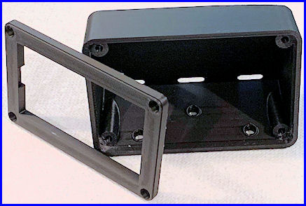
    I checked into the process and found I needed to take a Tutorial and a short Quiz, then sign a waiver to use this service.  That took only a short time and acquainted me with the 3D printing process.  I copied the necessary files from Thingverse to a USB Thumb Drive and took it and my completion certificate from the Tutorial plus the waiver to the library.  They said it should take 2 hours to print it and I could come back the next day to pick it up.  I did and they charged me $1.40 for the filament that was used.  Amazing!
 
    The case was printed in 2 pieces (back and front cover) see image on the right of the completed 3D print (click on any image to see it larger).  Once I had it home, a half hour of trimming off any excess plastic gave me the parts I needed to mount the meter.  A trip to the hardware for some 3mm hardware to mount the front cover and I was in business. 

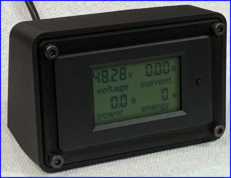
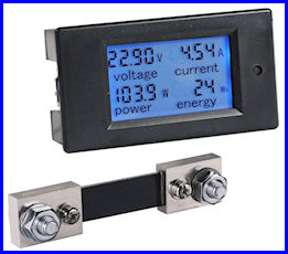
    Once I had the case cleaned up and the necessary mounting hardware, I needed to wire the meter shunt to the power supply and connect the the four wires from the Current Meter to the shunt and the positive terminal of the Mean Well power supply. 

    As you can see in the final photo, the meter is now mounted in the 3D printed case and is ready to by used in my 23cm EME system to monitor the 48VDC power supply and the current being supplied to the AG6EE Power Amplifier.  The photo at the top of this page shows the meter with the backlight on but it was difficult for me to get a usable photo with the backlight on.

Saturday, September 6, 2025

Adding a Leo Bodnar GPSDO to the IC-9700

GPSDO Injection Board Installed

Since the Icom IC-9700 can experience significant frequency drift, especially on 23cm, and this drift can affect digital modes -- I decided to add a GPS Disciplined Oscillator (GPSDO) to the radio.  Leo Bodnar offers such a device which connects to the radio's "REF IN" connector and supplies an external 49.152 MHz signal (derived from GPS satellites) to lock the transceiver's internal frequency reference to a stable signal.  This will insure the radio will stay within 1 Hz on all bands.

The product I purchased is the High Stability Kit for ICOM-9700 from Leo Bodnar.  This comes with the LBE-1420 GPSDO locked clock source which is a GPS receiver, an antenna for that receiver, an injection board for the IC-9700, and appropriate cables.  In the photo on the left (click for a larger image) you can see the injection board "1" installed (and outlined in yellow), the SMA connector for the GPS receiver "2" placed in the "REF IN 10MHz" location, and the original SMA connector "3" which was removed and taped to the inside of the radio.

The Leo Bodnar website has instructions for opening the radio and installing the injection board.  It is important to use the proper screwdriver, a Japanese Industrial Standard (JIS)  #2 and not a Phillips screwdriver to remove the 12 screws from the radio.  My only boo-boo was that I removed the 12 screws from the TOP of the case and not the BOTTOMDUH!  I wasted 15 minutes doing that.  Otherwise, it took me 1-1/2 hours to locate the tools needed, perform the install, and return the tools to the garage.  I was helped a bit by a video on YouTube describing the install and the setup of the device and the radio and also this YouTube video.

I did not have a frequency generator to produce a tone for fine tuning of the "REF Adjust" menu item in the IC-9700.  I did find a birdie and made some minor adjustments using that.  However, once I can source a relatively accurate signal source, I will do that part of the setup again.

This part of my 23cm EME project was pretty simple and took very little time.  Hopefully this will insure that my radio is on frequency and not drift.  This should allow me to make a few more EME contacts or make them more quickly.