Showing posts with label EME. Show all posts

Sunday, March 29, 2026

How I Configured my 23cm EME Station for PTT

Here is how I manage the PTT keying of my 23cm EME station.

Software/Equipment:  WSJT-X - Icom IC-9700 - AG6EE Power Amplifier/Preamp

WSJT-X controls the IC-9700 for PTT via CAT commands.

In WSJT-X under File | Settings | Advanced, I have "Tx delay" set to 0.4 seconds.

In the IC-9700 under Set> Function > TX Delay, it is left at the default of OFF for 1200M band.

Using the ACC1 connector on the rear of the IC-9700, I connect the SEND line through a relay to the PTT input on the AG6EE amplifier.  As the AG6EE amp has sequenced DC voltage to feed the preamplifier through the coaxial cable and the AG6EE preamp has a built-in relay and dummy load, I have no need for any other "outputs" from a traditional sequencer.

Click on the image on the right to see it larger.

Saturday, January 31, 2026

23cm EME Equipment - Block Diagram


Above is a block diagram of my 23cm EME station.  Click on it to see a larger image.  Note that the Leo Bodnar GPSDO injection board is actually installed inside the Icom IC-9700.  (See this Post - Leo Bodnar Installation)


All my 23cm EME Equipment "lives" on a 3-shelf rolling cart which stays in the garage along with my folding dish antenna.  When I plan to operate on EME, I simply roll out the cart, install the 2.4m folding dish, and connect the cables.  There are 3 cables from the Sub-Lunar SL-1 Az-El rotors to the WinTrak controller - the SEI controller Bus plus the Azimuth and Elevation power cables.

Then there are the two RF coaxes (Tx and Rx) which connect from the dish to the AG6EE power amp.  The Rx cable connects to the AG6EE preamp and the Tx cable to the OK1DFC Septum feed.  The TX cable connects thru the sensor of the WaveNode RF Power Meter and to the output of the AG6EE power amp.  The Rx cable connects to the AG6EE power amp which has sequenced DC voltage to feed the preamplifier through the coaxial cable.  The preamp also contains a built-in relay and dummy load and it connects directly to a septum or patch feed without the need for an adapter or coax jumper.

Once everything is connected, it is time to calibrate the dish's pointing location.  If the sun is not available, I can use the Theodolite app on the iPhone to get the Az and El of the moon and enter that into WinTrak.  If I have the sun, it is simpler to point the dish at the sun so that the square shadow of the Septum Feed appears on the exact center of the dish.  Then I press the calibrate button on the WinTrak software of the WinTrak controller and it will keep the dish pointed at the moon all the time.

You can see a 45-second video of me setting up the entire station on another Blog post "Setting Up the 23cm EME Station." There is a link in that Post to the video.  Clicking on that post will open in a new window. The setup of all the equipment actually took 19 minutes but the video was compressed to just show the basic operations.

Below is an image showing how the sun's shadow appears on the center of the dish for calibrating the antenna.


Saturday, January 10, 2026

Setting Up the 23cm EME Station

My 23cm EME station is not "permanent."  It is essentially a "portable" station.  All the equipment is located in my garage.  The 2.4m folding dish lays on the floor along with two AC extension cords plus the M&P TX and RX coax cables, and the rest of the equipment is on a 3-layer rolling Service Utility Cart. 

To set up the station, I roll out the utility cart containing the equipment plus an office chair, roll out and connect the AC cords, and power on the laptop, the PowerWerx 13.8VDC supply, and the WinTrak controller.  Next I install the SubLunar SL-1 Az-El antenna controllers on the tripod which is tied down to the edge of the driveway and secured with a spiral Earth Anchor.  Next I mount the folding dish to the SL-1 mounting bracket and connect the SEI bus and Az-El power cables from the SL-1 to the WinTrack Antenna Controller. Next I start the WinTrak app on the laptop. Now I unfurl the dish (a step ladder and yard stick is helpful to make sure the perimeter wire on the dish is not caught on anything.)   Once the perimeter wire is clear, I expand the dish to stress it into a parabolic shape and lock it into place.  Next I tell the WinTrak controller to bring the dish down to where I can connect the TX and RX cables to the OK1DFC Septum Feed and to the AG6EE power amplifier.

At this point, the equipment is connected and ready to use.  I shot a video of this process and then compressed it to a total running time of 45 seconds.  The actual setup of the dish and equipment took 19 minutes.  You can view the video here: Antenna Erection Video.  This video will open in a new window.


Sunday, October 26, 2025

First 23cm EME QSL's - KB7Q & DK3WG

After completing 50 "Initial" QSO's (contacts with 50 "different" stations) in just 2 days of operation, I was really looking forward to receiving some 23cm EME QSL's.  Well, Gene, KB7Q, was the first to satisfy that "itch" by sending me his QSL (See above.  You can click on the image to see it larger.)  What a THRILL!  This is my FIRST EVER QSL for 1296 MHz and my first EVER for an EME contact on that band.  WOW!  Thanks so much Gene.

I should also mention that over the past several months I have leaned heavily on Gene for advice on putting together my 23cm EME station.  He has always been there for me with the answer to nearly every question I posed.  So, a BIG THANK YOU, Gene for being my mentor on this new adventure.  I really appreciate your efforts.

Then, just 4 days later, I received a direct mailed QSL from Germany!  DK3WG even sent me a SAE plus $2 US currency for the return of my QSL!  Of course I will send the $2 back to him when I mail him my new 23cm EME QSL.  It's fun to feel like you are rare DX!!!

But, sadly, just 2 days after I received the above QSL from Jürgen his son sent me an email telling me that his father had passed away last week at the age of 82 due to a heart attack!  What a loss!

Wednesday, October 22, 2025

23cm EME QSL

Now that I have made multiple QSO's on 23cm EME, I realized I would need a new QSL.  So, I quickly ordered them from UX5UO QSL who I have used several time in the past.  Gennady is AWESOME and returned proofs to me actually just 2 hours, 20 minutes after I sent my order!

He said I could expect delivery in 3-5 weeks which is amazing to me, especially considering he is located in Kyiv, Ukraine!  While I'm waiting on the cards to arrive I'll be printing some envelopes so I can get the new cards in the mail ASAP.

As always, you can click on any image to see it a bit larger.

The "Diamond Ring" image of the moon on the QSL is a photo I took during the 2017-08-21 Solar Eclipse in Sweetwater, TN.  One of the top 5 events of my life! 

The other image on the QSL shows the operating position on my driveway.  The laptop is inside the Sun Shield so that I can more easily see the screen in daylight.

23cm EME Project - SUCCESS!

WHEEEEEE!  My efforts on building the 23cm EME station have been rewarded in a spectacular manner.  I am now active on 23cm EME for the VERY first time.  Over the last 37 years I have made EME QSO's on 6m, 2m, and 70cm but now with a 2.4m Sub-Lunar folding dish, I have managed my first EME contacts on this new (to me) band.  I was only able to be on for the 2nd night of the October ARRL contest weekend (2025-10-12) but managed 37 contacts, all new initials, in 17 DXCC's with OE9ERC, OK1DFC, RD4D, OK1UGA, K0PRT, G4YTL, N1AV, SP5GDM, HB9Q, OK1KIR, SM6CKU, ES3RF, OK2AQ, DF2VJ, KB2SA, YO2LAM, OK1USW, DK3WG, PA3FXB, GM0PJD, UA1ALD, WA3RGQ, DL0SHF, OH3LWP, SP3YDE, G4CCH, PA0TBR, AA6I, CT1FFU, KH6FA, W3TI, N0AKC, OH1LRY, AC2AC, K5N, W2ZQ, and JJ3JHP.  I had 7 decodes of PYØFBS as strong as -23 and 12 consecutive decodes of HL2/LY3UM (4 of those at -23) but no QSO's resulted with either of these fine DX'peditions. 

Operating Position on my Driveway
Because my QTH is blocked by trees to the East, my operating location is "portable" on my driveway.  The equipment is kept on a 3-shelf rolling cart which I wheel out of the garage to operate.  I am not able to see the moon until it clears my roof at about 22° elevation but I can see it almost down to the western horizon.  My QTH is EM98al in the state of West Virginia (WV).  

My equipment consists of: a 2,4m Sub-Lunar folding dish, OK1DFC Lightweight Septum Feed, Sub-Lunar SL-1 Az-El Rotors, N8CQ's WinTrack, IC-9700 w/Leo Bodnar GPSDO, AG6EE preamp, 200-watts from an AG6EE Power Amplifier, and 6,5m feed lines from Messi & Paoloni in Italy. However, since the station is "portable" there is the possibility that I can operate from other locations.  

I operated the next Saturday (2025-10-18) and made 16 QSO's including 13 more Initials: G0LBK, CX9BT, DL4DTU, PA0PLY, KA1GT, I2FAK, KB7Q, NY1V, OK1VUM, N5TM, F5KUG, VK2JDS, and XE1XA.  That brings me up to 53 QSO's, 50 Initials, and 22 DXCC's after only 2 days of operation on the moon.  Boy, am I fired up with those results!  I know I worked at least a couple of stations using 1,5m "Solar-Cooker" dishes and I worked KB2SA with his 1,0m dish, TWICE!  On the first KB2SA QSO reports were: Sent -21 / Rcvd -24. And, I easily completed a Q65-15A QSO with KA1GT, Sent -17 / Rcvd -15. 

With the overnight temperatures around 7°C both times, I have now ordered a portable hunting shelter to keep the operating position a bit more comfortable!  But, it has now occurred to me that I can actually operate the station remotely from INSIDE the house!  I will be working on that idea next.

Even though I have made hundreds of moonbounce QSO's over nearly 4 decades, the THRILL is still there!  Had any of my neighbors been awake at 12:45 a.m. when I made that first 23cm EME contact, I'm sure they would have heard my yell as I jumped up and down on the driveway!  WHOPEEE!

Monday, October 6, 2025

New Feed Lines for 23cm EME


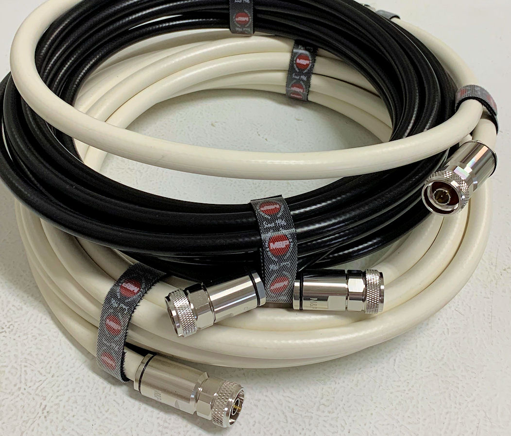
New feed lines were going to be required for my 23cm EME station.  For transmit I needed something that could handle as much as 700-watts on 23cm.  For several years I have depended on coaxial cable which is built in Italy by Messi & Paoloni.   They have been producing cables since 1984 and have received very good reviews.  I have made multiple purchases from M&P and have always been amazed at the quality of their cable and connectors.  For my transmit cables I decided on their HYPERFLEX 13 /.500" which is rated to handle 786 watts on 1296 MHz.  For my receive cable I chose their ULTRAFLEX 10 /.400" which is a little smaller and lighter.  I ordered a 6.5 m section of each cable with Solder type "N" connectors installed on BOTH ends.  I also ordered a 1.1 m piece of the larger cable as a jumper from the amp to the wattmeter.

The center conductor of the HYPERFLEX 13 contains 37 wires!  That makes it a very flexible cable. Click Here for a video showing how they install a soldered (or solderless) "N" Connector.  Their connectors are designed specifically for their cables.

I placed my order by email in the evening on September 29th, well after M&P had closed for the day.  In the morning of October 1st (1-1/2 days later) I had a response where they told me the HYPERFLEX cable with the black jacket was out of stock but they could supply their HYPERFLEX 13 Sahara with a white jacket.  Both cables have the same specifications but the Sahara cable has a white jacket to help reduce the attenuation degrading which a black cable can experience as the ambient temperature increases.  I quickly agreed to have the white jacketed cable substituted in my order for the HYPERFLEX 13 cables.  Just after midnight (my time) on October 2nd, I received the order confirmation and a PayPal link for me to make the payment.

Unbelievably the cables arrived at my QTH in the afternoon of October 6th.  Just 7 days after I placed the order!  WOOF!  Can you believe three custom-built coaxes with Soldered "N" connectors installed, were produced and DELIVERED from Italy in just 6 days?  Well, in my experience, this is NOT unusual!  My previous orders have taken only 6 or even 5 days to have connectors installed on custom lengths of cable and shipped from Italy to West Virginia.  

Click on the photo of the cables on the right for a larger view.  You can easily see the quality of the Soldered "N" connectors.  I continue to be very happy with the cables and connectors I purchase from M&P.  And I do not hesitate to recommend them.

Sunday, September 28, 2025

3D Printed Case for Amplifier Current Meter

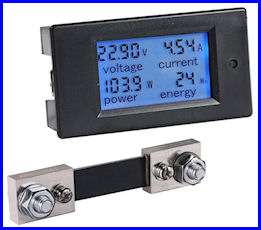
    In order to monitor the current being pulled by the AG6EE 23cm Amplifier, I purchased a Bayite DC 6.5-100V 0-100A LCD Display Digital Current Voltage Power Energy Meter Multi-meter Ammeter Voltmeter with 100A Current Shunt for $17.99 from Amazon.  That looked like a near perfect solution.  However, I did not want to just have that small (3.5"x2"x1") meter just lying around on the shelf or the top of the amp.  So, I searched for a box that I could mount that meter into and by chance came upon EXACTLY what I wanted as a 3D Print called "Power Monitor case V2" on Thingverse. Now the problem became "How Do I Print This?" since I do not own a 3D Printer.  Again, Mr. Google let me know that the Kanawha County Public Library has an area called the IDEA Lab where they will print 3D Digital Models and only charge for the filament used.  WOW!  
 
    I checked into the process and found I needed to take a Tutorial and a short Quiz, then sign a waiver to use this service.  That took only a short time and acquainted me with the 3D printing process.  I copied the necessary files from Thingverse to a USB Thumb Drive and took it and my completion certificate from the Tutorial plus the waiver to the library.  They said it should take 2 hours to print it and I could come back the next day to pick it up.  I did and they charged me $1.40 for the filament that was used.  Amazing!
 
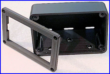
    The case was printed in 2 pieces (back and front cover) see image on the right of the completed 3D print (click on any image to see it larger).  Once I had it home, a half hour of trimming off any excess plastic gave me the parts I needed to mount the meter.  A trip to the hardware for some 3mm hardware to mount the front cover and I was in business. 

    Once I had the case cleaned up and the necessary mounting hardware, I needed to wire the meter shunt to the power supply and connect the the four wires from the Current Meter to the shunt and the positive terminal of the Mean Well power supply. 

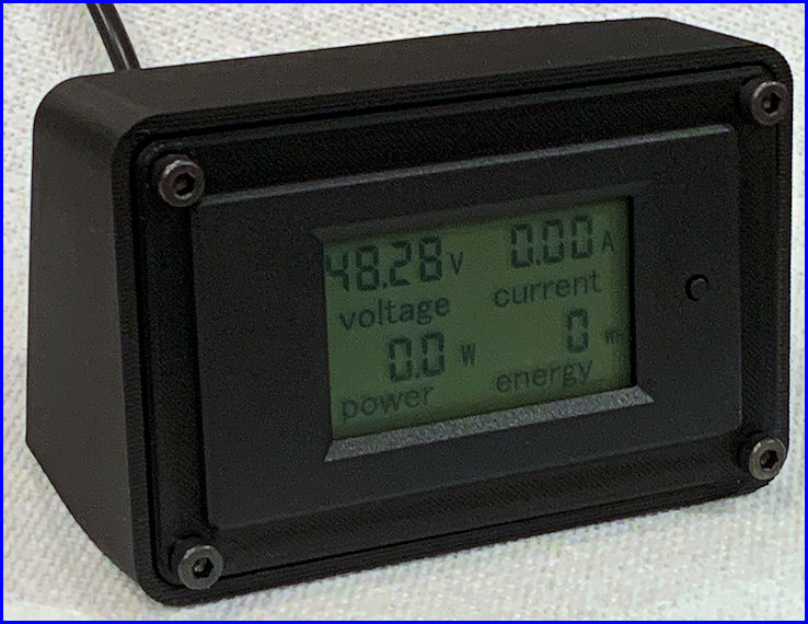
    As you can see in the final photo, the meter is now mounted in the 3D printed case and is ready to by used in my 23cm EME system to monitor the 48VDC power supply and the current being supplied to the AG6EE Power Amplifier.  The photo at the top of this page shows the meter with the backlight on but it was difficult for me to get a usable photo with the backlight on.

Saturday, September 6, 2025

Adding a Leo Bodnar GPSDO to the IC-9700

GPSDO Injection Board Installed

Since the Icom IC-9700 can experience significant frequency drift, especially on 23cm, and this drift can affect digital modes -- I decided to add a GPS Disciplined Oscillator (GPSDO) to the radio.  Leo Bodnar offers such a device which connects to the radio's "REF IN" connector and supplies an external 49.152 MHz signal (derived from GPS satellites) to lock the transceiver's internal frequency reference to a stable signal.  This will insure the radio will stay within 1 Hz on all bands.

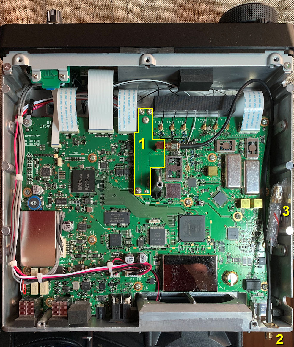
The product I purchased is the High Stability Kit for ICOM-9700 from Leo Bodnar.  This comes with the LBE-1420 GPSDO locked clock source which is a GPS receiver, an antenna for that receiver, an injection board for the IC-9700, and appropriate cables.  In the photo on the left (click for a larger image) you can see the injection board "1" installed (and outlined in yellow), the SMA connector for the GPS receiver "2" placed in the "REF IN 10MHz" location, and the original SMA connector "3" which was removed and taped to the inside of the radio.

The Leo Bodnar website has instructions for opening the radio and installing the injection board.  It is important to use the proper screwdriver, a Japanese Industrial Standard (JIS)  #2 and not a Phillips screwdriver to remove the 12 screws from the radio.  My only boo-boo was that I removed the 12 screws from the TOP of the case and not the BOTTOMDUH!  I wasted 15 minutes doing that.  Otherwise, it took me 1-1/2 hours to locate the tools needed, perform the install, and return the tools to the garage.  I was helped a bit by a video on YouTube describing the install and the setup of the device and the radio and also this YouTube video.

I did not have a frequency generator to produce a tone for fine tuning of the "REF Adjust" menu item in the IC-9700.  I did find a birdie and made some minor adjustments using that.  However, once I can source a relatively accurate signal source, I will do that part of the setup again.

This part of my 23cm EME project was pretty simple and took very little time.  Hopefully this will insure that my radio is on frequency and not drift.  This should allow me to make a few more EME contacts or make them more quickly. 

Thursday, August 7, 2025

Theodolite Application for Locating the Moon

Theodolite is a multi-functional app that combines a compass, inclinometer, rangefinder, GPS, map, and camera with geo-overlay for augmented reality. It's essentially a digital theodolite, allowing users to measure angles, distances, and positions using their smartphone or tablet.  This is the perfect way to locate the moon in azimuth and elevation for pointing the antenna.  I purchased this app from the Apple Store for $9.53 and in my opinion it is well worth that price.

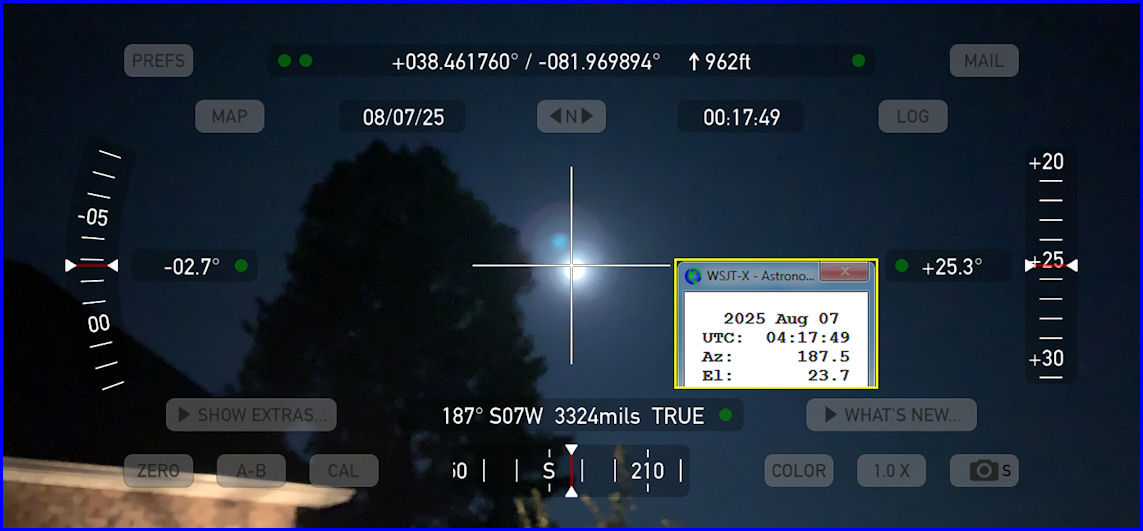
Below is my first attempt at using this app to locate the moon.  Local time was just after midnight and Full Moon is in 2 days so this moon was over 90% illuminated - it is bright!  You can see a tree to the left of the moon and also a portion of the edge of my garage.  This image was taken at the point where I plan to set up my Sub-Lunar Folding Dish.  At the time I took this photo the declination was -27° so the moon was not very high in the sky even though it was nearly due South of me.  You can see that the Horizon Angle on the left shows the phone was tilted 2.7° away from horizontal.  (Click on any image to see a larger version.)

I placed inside the Theodolite image a Yellow bordered box showing the Astronomical Data from WSJT-X for the same date/time.  You can see the app shows an Azimuth of 187° and WSJT-X shows 187.5° and since the moon is actually below the crosshairs, the indicated Elevation Angle on the right (of +25.3°) was a little off from the WSJT-X number of 23.7°  At the top of the screen the app also shows my latitude/longitude and elevation. 

I learned that I might want to set my iPhone on a tripod to keep it steady in the future.  Just holding the phone in my hands it was difficult to center the moon in the app.  Also, you can push the "Zero" button in the bottom left and it will put a box around the crosshairs in the center of the image.  This box changes color from Red to Yellow to Green then White as you get the image lined up with the horizon so the elevation numbers are correct.  What this button does is to zero all angles at a given orientation of the device, thereby showing angles relative to that reference until you tap the button again.  Once you tap zero again the true angles will be displayed and if the phone has not moved, the Elevation Angle will be correct (as long as the moon is centered in the crosshairs!) 

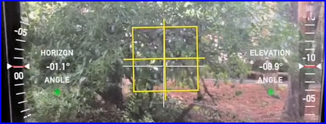
In the example below the Elevation Angle on the right shows -08.9° but the Horizon Angle on the left shows the image is -01.1° from being level.  And, the yellow box shows you are close to being lined up.  If you line up the image and "then" press the Zero button, it will adapt the image so that the Horizon angle is 0.0°


I don't think this app will take much effort to be able to dial in the location of the moon.  Once I have those numbers, I can set up my SL-1 Az-El Positioner to the current moon location and "hopefully" it will then track the moon automatically.  If I don't have visible moon, I "think" I can still use this app to align it with the dish feed and use that as the starting position for the Az-El Positioner.  The Theodolite User Manual is located HERE.

New EME Challenge - 23cm

In the late 1980's I had four CushCraft A32-19 yagis and a kW for my first ever EME activities on 2-M.  I managed to make 5 QSO's (CW) including K1FO and WA1JXN/7 (Now W7GJ!) before the antennas fell.

From 1992 to 1995 I operated 70cm EME beginning with my first ever 70cm EME QSO - DL9KR on 18-October-1992.  This was before WSJT or JT65 were invented so almost all QSO's were CW except for one on SSB with VE3ONT who was operating a 150-foot dish antenna!  I used four K1FO 25-element yagis and a kW and I made at least 74 "Initials" on 70cm EME.

In November 2017 I installed two 13-L InnovAntenna yagis for 2-M and with a kW from a W6PQL amplifier, over the next 6 years I completed 345 EME QSO's with 278 "Initials" and 64 DXCC Entities.  That station is now temporarily QRT due to a failure in the elevation mechanism.

In 2022 and 2023 I was able to make a couple of EME QSO's with KJ9I on 6-M.  I was using an 8-L InnovAntenna LFA2 yagi at 28m AGL with up to 1.5kW.  But, although Lance, W7GJ, heard me on 3 of his DX'peditions, I was never able to hear him.

Now, after having completed EME QSO's on 6-M, 2-M, and 70cm, I felt it was time to explore a new EME band - 23cm (also known as 1296 MHz.)  Over the past few years there have been huge improvements in equipment for this band and it is possible to purchase all needed items off-the-shelf without the need to "home-brew" any of the needed equipment.  I had delayed moving to this band for several years because my location was not suitable for a parabolic dish antenna (mounted on the ground) to see the moon in the part of the sky which favors Europe.  Too many trees!  However, Paul Andrews, W2HRO, has developed and is marketing a lightweight, folding parabolic dish which uses space-age RF reflective fabric.  His company, Sub-Lunar, sells folding dishes in several sizes, patch feeds, OK1DFC Septum feeds, WinTrack Software/Hardware from N8CQ, Az-El positioners, and many other products to support EME operation.  This "portable" dish concept allowed me to consider other locations on my lot where I could "temporarily" install the antenna with a better view of the moon.
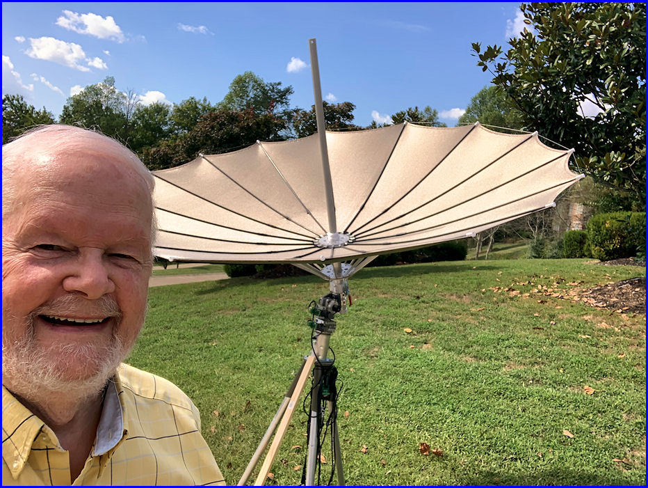
I decided to go with a 1.8m dish (just under 6-feet in diameter) because it was lighter and easier to install and remove.  The 2.4m dish would add about 2 dB to TX and RX signals but I was concerned that I might not be able to handle that larger antenna by myself.  The antenna folds and unfolds like an umbrella!  But it is not weather proof in any of its components and is sensitive to wet and wind!  For that reason, it is a "temporary" antenna.  I plan to only use it when the weather and moon conditions are favorable. UPDATE 2025-08-20 - After talking to several EME'ers and checking with W2HRO at Sub-Lunar, I opted to change my folding dish order to a 2.4m version.  Paul (W2HRO) said he felt I would have no problems with the larger dish.  The earlier models were a little tight but no more.  Bigger is better they say!  -  As it turned out, I was able to install the 2.4m dish just fine!

Considering this would be a "temporary" set-up, I decided to purchase a rolling cart that could hold all the equipment (power supplies, amplifier, laptop, etc.) and thus it would be extremely simple to just roll the cart out of the garage, erect the antenna, connect the feedlines, and be on the air.

A recent improvement in folding dish setups is the OK1DFC Lightweight Septum Feed.  Originally those stations with a folding dish used a "Patch Feed."  But on 23cm (1296 MHz) EME signals use circular polarization.  In order to get circular polarization from a patch feed, you need to incorporate a 90° hybrid to provide circular polarization. However, to switch between LHCP (Left-Hand Circular Polarization) and RHCP (Right-Hand Circular Polarization), a power relay and a set of cables are also required.  A key advantage of the septum feed is its ability to generate both RHCP and LHCP simultaneously!  This eliminates the need for a 90° hybrid.  Also many hybrids are not exactly 90° so that results is less than optimal operation.  And, 90° hybrids are limited in the amount of power they can handle - often only in the 200-watt range. 

Other major components include a preamplifier and a high power amplifier.  Thankfully AG6EE has been building both.  His pre-amp has about 30 dB of gain, with a built-in relay and dummy load - and can connect directly to septum feed without a jumper.  His 23cm amplifier is spec'd for 600W out (max 700W) and splits the input into TX and RX lines, the RX line has sequenced DC voltage to feed the preamplifier through the coaxial cable. 

Since I have not operated on 23cm for 24 years (and all that equipment is gone) I needed to acquire a transceiver to operate on 23cm.  I chose the Icom IC-9700.  There is a know frequency drift problem with that radio on 23cm so I ordered a GPSDO from Leo Bodnar to incorporate inside the IC-9700 with an external GPS antenna included. In order to install the Leo Bodnar injection board inside the IC-9700, it is necessary to open the case of the radio.  That requires a special screwdriver. A P2x100 #2 JIS Cross Point Impact Screwdriver is what I ordered from Amazon. And, a laptop would also be required so I purchased a refurbished Dell 5500 Win10 from Amazon utilizing an 8th Generation Intel Core i7 with a 512GB SSD Hard Drive and 32GB DDR4 RAM.  To power the radio and the pre-amp I bought a PowerWerx 30A 14.1 VDC Power Supply, and to power the amplifier, I purchased a Mean Well RSP-2000-48 VDC Power Supply from DigiKey.

Several other minor items were also purchased - a 23cm Coaxial Dynamics 1kW element for my Bird 43 wattmeter, a WaveNode® WN-2m digital wattmeter with 500-watt 23cm sensor, 6.5m feed lines from Messi & Paoloni in Italy, a 50-foot 12/3 extension cord, an AC power strip, a spiral ground anchor to hold the dish tripod down, an LED keyboard lamp, a Shielded/Filtered USB Cable for the IC-9700, and so on.  Then a fair amount of time was spent downloading and installing multiple pieces of software on the computer.  I worked on this project every day with the goal of being operational on 23cm EME in time for the ARRL EME Contest on October 11/12.  Fingers crossed! = SUCCESS!  I am now operational on 23cm EME!!!!!!!

Tuesday, March 7, 2023

ZC4RH - British Military Bases, Cyprus - 2-M EME

Today I received a QSL for my QSO with ZC4RH on 2-M EME!  This is my 63rd Country confirmed on 2-M EME with one more worked but not confirmed (VK.)  (Click on any image to see it larger.)


Chris, PA2CHR, Jos, PA3FYC, and Dave, ZC4RH, set up and operated an EME station on three VHF bands in November 2022 from an extremely rare location.  The British Bases on Cyprus occupy only about 98 square miles so it's quite small.  This operation took at least a year of planning, on-site visits, pre-shipment of all equipment by UPS/DHL, and loads of preparation.  Many difficulties had to be overcome but the final result was a huge success.

The ZC4RH operation ended with: 144 MHz:  213 QSO's    /     432 MHz:    54  QSO's   /    1296 MHz:   32  QSO's

For 2-M the ZC4RH station consisted of: FT857, SSPA, LNA and 2 x 10/10 ele x-pol yagis (16 dBd).  My own 800-watts and 2 x 14/14 XPOL InnovAntennas was sufficient to finally make the QSO - just moments before their MoonSet on the final day of 2-M operation.


I am just SO excited to have added this very, very rare entity to my list of countries worked and confirmed via 2-M EME!  Opportunities to work such stations come along seldom so to check this one off is a HUGE satisfaction to me. My sincere THANKS to Chris, Jos, and Dave for all their efforts in making this happen!

Previously I have worked Chris, PA2CHR, and Jos, PA3FYC, from TD9FYC (2018) and VP2EMB (2019) as both New Countries for me.  I'm anxiously waiting to see where they go next!

Wednesday, September 7, 2022

Another Cable Order from Messi & Paoloni

As I am getting close to completing my new antenna array (a pair of 14-element InnovAntenna XPOL yagis) I wanted to make sure I had the best possible cable to connect my antennas to my station.  Of course, in my opinion, there is ONLY ONE choice for that - Messi & Paoloni from Italy.  If you visit their website you will see a pop-up showing that you can now purchase their products from GIGAPARTS and BUY TWO WAY RADIOS.  However, since I have made several purchases of custom cables direct from M&P, I chose to do that again.

Instead of buying a standard length of a particular cable, I ordered cables to fit the place where I needed them and, I had their best quality "N-Male" connectors SOLDERED on to the ends of the cable.  Since my station is already using the ULTRAFLEX 10/.400" cables to run from the LNA's to the LinkRF IQ+ dual channel receiver, I chose that same cable for my jumpers from the Power Dividers to the T/R relay.  I also purchased a couple of 3-foot jumpers for use in the shack.

I placed the order on August 31 and received all the cables on September 6, 2022 - less than a week from Italy!  It would have been even sooner but the Labor Day weekend intervened.  Below you can see 2 of the cables I ordered (a 1m and a 4m) complete with the "Test Results" for each cable!  AWESOME!


Saturday, August 20, 2022

Custom-Made Driven Element Measuring Tool

In tuning my InnovAntenna LFA 2-M yagis (and later my XPOL antennas) I needed a simple way to measure the Driven Element (DE) dimensions.  The manual for my 2-M antennas says:

Hose clips are ready to place on the driven element sections and need to be loosened to allow the insertion of the end-loop element sections. The loop end sections are easy to identify and once inserted should be tightened to around 0.890m from the inside of the loop section one side, to the inside of the loop section on the other side. This loop will need adjusting once the antenna is complete with the above measurement being the starting point.

According to the manual for my 2-M antennas above, the DE loop sections should initially be set to around 0.890m from the inside of the loop section on one side, to the inside of the loop section on the other side.  I found it really difficult to measure this distance across the square boom while I was trying to adjust them.  So, I measured the width of the boom at 38mm and deducted that from the 890mm total distance (890 - 38 = 852mm).  Dividing that by two gives 426mm from the inside of the DE to the closest side of the square boom.  

The solution thus became obvious.  Since the antenna boom is square, a tool could be built to measure from the closest side of the boom to the inside of the DE loop.  So I took a short length of 1/2" X 1/2" wooden molding and taped a printout of a millimeter scale to it.  The printout of the mm scale was not 100% accurate but I decided it would serve perfectly as a "relative" measuring tool.  That is, if I measure one Driven Element at 426mm according to this tool, I could measure another to 426mm and they would be the same.  It would not matter if the distance was actually 427mm.  Just being able to adjust the corners of each DE loop to be the same distance and then adjust the DE loop on the other side of the boom to be the same was my goal.  I positioned the printout on the wooden stick so that the "Ø" on the printout was exactly 300mm from the far end.  That made it easy to adjust the DE's to the initial setting of 426mm (just add 300mm to the scale reading) and then move the DE's in easily repeatable amounts.  (Click on any image to view a larger size.)

Custon-Made Driven Element Measuring Tool

All I had to do was to place the end of the wooden stick on the side of the square boom and then measure to the inside of the DE using the scale on the measuring tool.

DE Measuring Tool in Use

Once I tightened the hose clamp (Jubilee Clip in the U.K.) on one end of a DE, it was extremely easy to move the measuring tool to the other end, adjust it to the same measurement and then tighten that hose clamp.  This made the adjustable portion of that DE square to the boom.  Then I just used the same measurement on the tool to set the DE on the other side of the boom.  Simple!  I sure wish I had thought of this back in 2017 when I was trying to adjust my 13-L antennas!

And, after I posted the above, Carlos, WD6Y made a similar tool for 70cm:


Wednesday, December 30, 2020

Sycamore Tree Removal

Damaged DE
I have a "forest" of trees directly East of my EME antennas.  In the winter when the leaves and sap are gone, it seems not to be a huge problem to my moonbounce operations, but in the spring and summer it provides a "brick wall" that keeps me from hearing all but the very strongest EME signals.   Two of these trees (directly behind the house) are Sycamores.  It turns out that Evelyn is severely affected by the dust these trees develop under their leaves in the summer.  If she steps out on the back porch, she will start exhibiting an allergic reaction in less than a minute!  Thus, these trees HAVE TO GO!

Once we decided to have these two Sycamores removed, we chose RealTree Tree Services (a local tree service) and they were able to schedule the removal for today.  I told them we just wanted to "drop" the trees over the lip of the hill where they sat.  Therefore they did not need to be cut up nor did we need the stumps ground down.  This kept the costs down.

These two trees were directly East of my EME array and provided significant blockage from 70° to 110° in Azimuth. This was the direction of my MoonRise and that's where I need to see the moon to be able to work stations in Europe. In the photo on the Top-Left you can see how close my antennas are to these trees even when the antennas are turned broadside to the trees.  And you get a bit of an ideal of how tall the trees are.  The tree cutters estimated the largest one was 65-feet tall.  The image on the Center-Right shows a better view to indicate the height of the trees.

Over the last 3 years I have been on EME, these trees have grown to the point where they prevent my antennas from pointing in their direction.  I first noticed this early in February of 2020 when my SWR suddenly shot up.  I tracked that problem down to the fact that the trees had reached out and GRABBED the driven element of one antenna and actually pulled it apart.  (See the image on the Top-Right of this Post.)  Click on any image to see it larger.

For multiple reasons I asked my Grandsons (Owen and Grant) to come down today to help out.  I knew they could clean the debris from the yard and could cut any of the trees that fell across the "trail" we used to access the HF tower.  They showed up about 8:15 a.m. and brought their friend, Logan, as well.  Evelyn had made a BIG breakfast for them with ham, eggs, biscuits, fried apples, hash browns, and hot chocolate.  After they ate (and the tree service had not arrived) I had them do a small amount of tree trimming at the mailbox.  Later I had them check our whole house generator and replace the battery in it.

When the tree service arrived, they saw that we had three strong men available so they cancelled their own ground crew.  The one guy that did all the major work then paid my "ground crew" $100 of what he had planned to charge me.  You can see on the Bottom-Left photo my Ground Crew cutting up the large tree.  It fell across the "trail" so they got to work with their chainsaws and cleared the way. Logan is on the left gathering up one of the ropes for the tree service guy.

Click HERE for a 30-second video of the trees coming down.  I was a little slow in starting the video for the large tree falling so it is not included.  That large tree definitely shook the ground when it hit.

There are still a LOT of trees to my East but I'm hoping that by removing these two large trees (which were so close to the antennas that the branches were touching the antenna elements) that my signals toward MoonRise will improve. Maybe it is wishful thinking but I feel like I can see more "sky" than I could before removing these two Sycamores. Time will tell. However, on Thursday morning I can tell there is a great deal more light coming into my bathroom. Those trees were definitely blocking a bunch of sky.

Monday, December 28, 2020

Weatherproof Cable Entry Port

Roxtec EzEntry™ 10/10
When I built my current EME antenna system 3 years ago, I used a PVC box to hold the T/R relay and the LNA close to the antennas (see photo at left.)  Since I was using cables which already had the terminations installed and I did not want to remove those connectors, my only option was to drill a hole large enough for the connector to pass through the wall of the box.  Those holes are marked by Purple arrows in the image.

As I began construction of my new XPOL array, I needed to purchase a new and much larger plastic box to hold the multiple relays (5 this time) and the two new LNA's.  Because I have purchased a pair of matched 1/4 λ cavity LNA's for this system, I need a MUCH bigger box than before.  These LNA's (click HERE to see them) are 17-inches long.

This new system will require FIVE large coaxes plus multiple control wires to enter the box.  In the old system I had THREE large coaxes and needed to drill holes in the box large enough to pass the connectors on the ends of the cables.  I was never able to manage to waterproof those large entry holes well enough to keep water out of the box.  As we all know, water is the enemy of electronic equipment.

Looking for a more elegant solution, I came across the Roxtec EzEntry system.  This solution provides a cable entry seal that can be used to weatherproof pre-terminated cables without the need for removing the terminations.  That is AWESOME! You can use any cables with connectors already installed and be assured the Cable Entry Port is weatherproof and insect-proof.  It is also a system that can be modified to add or remove cables with ease.

Different size cables are easily installed.  To adapt the sealing modules to different cable sizes, simply peel off layers from each half of the blue modules until it fits the cable.  It is important that you leave a  0.1 to 1 mm gap between the halves of the blue module when placed around the cable.  Unused blue modules can stay in the frame for use as "spares" in the future.  During installation all parts are lubricated with the supplied lubricant.  Click HERE for a 5-minute video of the installation process.

Module Installation
Once all the modules and cables have been installed, an integrated compression unit is tightened with a Hex key.  This compresses the modules for sealing, squeezes out the excess lubricant, and the installation is complete.

I was really excited to learn about this product which I believe will greatly improve my ability to keep water away from the relays and LNA's for my new array.  This system is available in many sizes but I decided to go with the Roxtec EzEntry™ 10/10 model.  It allows for up to 10 cables each ranging in size from 0.138-0.650 in (3.5-16.5 mm).  This is more than large enough to accomodate 1/2-inch Heliax which has a diameter of 0.51 inches (12.95 mm.) Overall size of the unit is 2.76 x 6.61 in (70x168 mm) which will easily fit my new box.

I also think it is important to note that you can install the Roxtec EzEntry frame in the box without the blue modules and run the various cable into the box through the frame.  Once everything is connected and positioned, THEN you can install the blue modules to seal the cables.  This makes the process very convenient.

I have found several suppliers of these products online.  The model I have decided to use (Roxtec EzEntry™ 10/10) is available for about $85 including shipping.  I feel that is a super low price to pay in order to weatherproof cables entering my Relay/LNA box.

Thursday, October 1, 2020

Moon Globe

For more than a year I have been serving as an "Elmer" to Carlos, WD6Y, in his efforts to build a 70cm EME station.  An "Elmer" is defined as a mentor; an experienced operator who tutors newer operators.

Recently Carlos sent me a photo of the current configuration of his station.  In one corner of the photo a Moon Globe caught my attention. (See photo at Left.  Click on any photo to see a larger image.)

In my next email to him I added the following post script:

   "P.S. I like the moon globe behind the IQ+ receiver!"

Yesterday my wife picked up the mail and there was a box from Amazon.  She asked what I had purchased and I said, "I'll have to open it and see because I can't remember having any orders outstanding."

Later that night I opened the Amazon box and found a Beautiful Gift Bag from Amazon.  I proceeded to carefully open the bag (so that my wife could re-use it at a later time if she wanted.)  Inside was the box you can see on the Right and I believe THIS is that product on the Amazon web site.

I waited until today to see about putting a battery in it.  But, when I started to open the battery compartment, I found there was just a small plastic tab I needed to remove to activate the included and installed batteries.  One pull and the Moon Globe lit up when the switch was flipped!

It did not take long for me to find a suitable place to put the lighted Moon Globe.  On August 21, 2017, I traveled to Sweetwater, TN, with my great friend, Karl, K8KT (SK) to view the Lunar Eclipse.  I took quite a few images (see the best HERE) but my favorite was the "Diamond Ring" photo and I had that one professionally printed.  As you can see in the photo on the Left, it now prominently hangs on the wall of my shack.  It is also on my EME QSL (see it HERE.)

I was totally SURPRISED to receive this thoughtful gift from WD6Y and can not be MORE THANKFUL!  The gift itself is a minor item but the thoughtfulness of the sender was immense! (Plus, my wife is especially appreciative for the Gift Bag!)

THANK YOU, Carlos!


Tuesday, October 8, 2019

Messi & Paoloni Coaxial Cable

Two years ago when first building my EME station, I purchased through GigaParts a 75-foot length of 400-UF cable with Male N-Connectors on each end which was built by ABR Industries and supplied to GigaParts.  This is cable which is apparently built for ABR Industries and is supposed to be "similar" to LMR400-UF but is actually marked as "ABR400UF" cable and NOT a Times Microwave LMR cable.  

This was to be the Receive cable from my preamp down to the shack.  It tuned out that the installed N-connectors were CRAP!  One of them was so difficult to screw on that I had to put a set of a double-female N-connector and a double-male N-connector on the shack end of the cable to allow the cable to be easily connected.

As I made more and more EME QSO's, I began to notice that quite a lot of the time I was receiving better signal reports than I was giving.  So, I tracked the QSO's where I had signal reports to see if my impression was true.

Out of 174 EME QSO's, 71.54% of the time I RECEIVED a better signal report than I gave.  That RECEIVED report was an average of 5.2 dB better than I gave.  21.14% of the time I GAVE a better report by an average of 3.0 dB.  7.32% of the time the reports were equal.  Now that I proved there was a substantial difference between signal reports received and sent, I began to suspect there was an issue with the ABR400UF cable and/or the N-connectors from ABR Industries.

Since I am now moving to an XPOL system with 2 preamps, I will need two receive coax cables.  I did not feel like using the current ABR400UF cable so I decided to look for something else.

Searching around I became aware of coaxial cable which was built in Italy by Messi & Paoloni.   They have been producing cables since 1984 and have received very good reviews.

In looking at the specifications on the M&P website, I decided to go with the "ULTRAFLEX 10" cable.  The main reason for choosing this cable is that it has a very high (Greater Than 105 dB) "screening efficiency" which is reported to reduce background noise more than other similar cables.  The shield effectiveness of the ABR400UF is Less Than 90 dB.  That's a BIG difference.  Loss per 100-feet at 144 MHz is 1.4 dB for the ULTRAFLEX 10 while the loss of ABR400UF at 150 MHz is 1.8 dB.  Not really a big difference considering I'm only using about 75-feet.

The N-connectors I chose for the M&P cables are their new generation ones with double sealing that protects even more from humidity, condensation and water.  The model is CO.N.10M-S and if you CLICK HERE, you can see the description of those connectors as well as a couple of videos showing how to install their connectors.  Also, you can click on any image on this page to see a larger version.

25m Cable as Received

Currently two 75-foot lengths of ABR400UF with N-connectors costs $213.90 and GigaParts would ship them for free.  Today I purchased two 25m (82-foot) lengths of ULTRAFLEX 10 with SOLDERED N-connectors installed direct from Messi & Paoloni for a total of $259.50 including shipping and PayPal fees.  So for an extra $45.60 I will at the very least have peace of mind and possibly MUCH better receive cables.

UPDATE: My order was placed on October 8th, it was shipped on October 10th (from Italy) and UPS says I should expect it Monday, October 14th.  Not bad at all!

2nd UPDATE: On Monday, October 14th, as expected, my package containing two 25m lengths of "ULTRAFLEX 10" cable with N-connectors factory installed was delivered by UPS.  Only 6 days after I placed the custom order and, it was shipped from Italy!  Besides the coax, M&P graciously included a couple of lens cleaning cloths with their logo on them.  NICE!  This is VERY good looking cable and I'm really excited to check it out.  Stay tuned for the results!

Monday, December 31, 2018

Moving the 2-M EME Antennas to Vertical Polarization

Horizontal Polarity for 13 Months
For the last 13 months I have operated 2-M EME with antennas that were fixed in horizontal polarization.  My two 13-element LFA InnovAntennas have been mounted "side-by-side" in a horizontal arrangement (see photo at left - click on any photo to see it larger.)  In an effort to see if I can expand the number of stations I have been able to work and maybe work a few New Ones, I decided to re-mount the antennas in Vertical Polarization.  Other EME stations I have talked with here in the U.S. tell me that they work more stations with Vertical Polarization than they do with Horizontal.  In that 13 months of operating with Horizontal Polarization, here are my 2-M EME totals as of November 26, 2018:

Antennas Are Down
   259 EME QSO's
   232 Initials (New Stations)
   185 Grids

   58 DXCC Countries Worked / 53 Confirmed

   U.S. States on 2-M
   44 Worked / 44 Confirmed
(not all via EME)

So, on 27-December-2018, with the help of my grandsons, Owen and Grant, we took down the two 13-element InnovAntenna yagis.  I then began the work of re-configuring the antennas so that they can be mounted in Vertical Polarization.

On 30-December-2018 the temperature was up to 49° F with a little sunshine so I proceeded with adapting the antennas for vertical mounting. This required removing and reinstalling the mounting bracket after rotating it 90°, doing the same for the truss mounting bracket, drilling two holes in each antenna for the truss cables to attach to the boom, and sealing the original holes in the boom.  I decided to locate the new holes for the truss wires 1-inch further away from the center of the antenna to not weaken the boom at that point.  Then, Scotch® Super 88 electrical tape was used to seal the old holes.

Cross Boom Mounting
Rotated for Vertical Mounting
Care was taken to make sure the truss cable was as far from the vertical elements as possible.  I achieved a spacing of 2-inches.  The truss cables are non-conductive but I wanted to avoid any close proximity to prevent transfer of rain/snow/ice and "critter" construction projects (spider webs.)  I also made sure that the antennas remained "in-phase" with each other (both antennas have the same side of the driven element in the same position.)  That is, the side of the driven element that is connected to the center conductor of the coax is pointing down on both antennas.  Both could have been pointing up but that's just how it worked out.  Care was also taken to make sure the mounting bracket for each antenna was positioned at the same point on both antennas. Finally, I drilled a 1/8-inch hole in the bottom rear corner of the driven element (which is constructed of tubing) to allow any condensation to drain out.

When the antennas were in horizontal polarization, the mounting brackets had the antennas sitting on top of the fiberglass cross boom.  I decided this time to allow the antennas to "hang" from the cross boom by the U-bolts when mounted in vertical polarization.  It may not make any difference but I thought it would make it easier for me to install the antennas with the nuts for the U-bolts now on the underside of the bracket.

The above work (including acquiring and replacing all tools) took four hours.  At this point all I need to do is to adjust the turnbuckles on the truss cables to bring the antenna boom into a horizontal position.  I also plan to construct two trusses for the cross boom in order to reduce the "droop" which has crept into the fiberglass cross boom.  That will be covered in my next Post.

Mounting Antenna
Adjusting Truss Turnbuckle
On Sunday morning, January 6, 2019, my grandsons, Owen and Grant, came to my QTH to help put up the antennas.  The temperature reached 50° and was partly sunny.  A very good January day.  First we mounted the antennas one at a time on a Workmate® "Portable Folding Work Support " in the vertical position.  Then, as you can see in the photo at the left, we adjusted the turnbuckles on the support truss so that the antennas were supported enough to keep the boom straight.  And added a Zip Tie to prevent the turnbuckles from loosening.

Once we had the first antenna complete, Owen and Grant installed it on the fiberglass Cross Boom.  In the photo at the right you can see them installing the second antenna on the Cross Boom.  We took care to make sure that the antennas remained "in-phase" with each other when we mounted the second antenna.

The difficult part was to tighten down the second antenna so that it remained parallel to the first antenna.  This took several tries until we all figured out how much we had to "over-compensate" when beginning to tighten the U-bolts.  Once we got that down, we quickly had the two antennas parallel.  The total time to do all of the work today was only 2 hours.  And, the thing I learned from when Tim, K8RRT, and I installed the antennas the first time in Horizontal polarization, was that having TWO people mounting the antenna makes it MUCH easier!  Also, using a small electric drill with the proper deep socket was a BIG improvement over just using a manual ratchet!

Once the antennas were installed, Owen adjusted the inclinometer so that it read the actual elevation (as measured by a digital level on the boom of one antenna.)  I was anxious at that point to raise the antennas to their final operating position until Grant pointed out that I had not connected the feedlines to the power divider!  DUH!  I'm sure glad these boys are understanding what we are doing so that they can keep old Grandpa straight!

Antennas are now Vertically Polarized
As you can see in the last photo, the left-hand antenna has just a little too much tension in the truss for the rear portion of the antenna.  When the grandsons are here later this week (when they are out of school), we will tweak that.  Also, I have completed the trusses for the fiberglass cross boom and maybe we can install them at that time.  That should (hopefully) eliminate the droop in the cross boom.

As I mentioned above, once I have installed the trusses for the cross boom, I will Post that info (with pictures) to this Blog.  Until then, I'm very anxious to try out the antennas in Vertical Polarization to see if I can work stations who I was not able to work when the antennas were Horizontally Polarized.  Moon conditions are not very favorable for the next two weeks but January 20-24 looks like some REALLY good moon conditions so you can bet I'll be in the operating seat whenever the moon is up on those days!

Saturday, December 29, 2018

Acquiring Equipment for Cross-Polarization Operation

My future plans for EME call for me to install cross-polarized antennas so that I will be able to change my antenna polarity at will.  That way I can transmit in either vertical or horizontal polarization and also receive the same way.  No longer will I be "locked out" of making a QSO because of polarity differences between my station and the station I want to work.

IQ+ Dual RX Radio
This switchable Dual-Polarity is a pretty big improvement for me.  But, there is another level of improvement beyond just being able to switch between Horizontal (H) and Vertical (V) polarization. This is call Adaptive Polarization.  It requires a good deal more hardware and software but does an amazing thing.  It combines the Receive signals from the H and V antennas, computes the vector angle of polarization and then peaks the output according to that polarity.  This completely eliminates polarity loss.

The first piece of hardware to accomplish this is the IQ+ from HB9DRI and his company, LinkRF.  This is essentially two receivers in one box with inputs for the H and V antennas.  The two receivers are "locked" together with the same Local Oscillator (LO) so that the output from each have the same amplitude and phase of the original signal.  These outputs supply the I and Q (quadrature) signals which are samples of the same signal taken 90 degrees out of phase. 

UADC4
Those I and Q signals are fed into the UADC4 (Universal Analog to Digital Converter) and then into the software.  The UADC4 is another product of LinkRF.  It replaces the PC audio cards traditionally used to interface between radios and computers.  However, the UADC4 is MUCH better than even the best PC audio card.  With the proper hardware ahead of it, the improvement can reach as much as 15 dB better performance yielding dramatic improvements in the noise floor!  (Click on images to see them larger.)

The software that does the amazing job of combining the H and V signals is called Linrad and is the creation of SM5BSZ.  Originally it was written in Linux but it is now available for Windows.  The output data stream from Linrad is sent to K1JT's Map65 software and this program provides a waterfall showing all signals in a 192 kHz passband, a WSJT type control panel for transmitting and decoding messages, plus lists of all the stations copied in the entire passband!  WHEW!

As the first step toward configuring my EME station to do all this, I have placed my order for a UADC4 and for the IQ+ revC (modified to work with the UADC4.)  I had previously pre-ordered the UADC4 some 13 months ago but it has taken this long to move the product from initial prototypes to final production.  My IQ+ and UADC4 are scheduled to be shipped about the end of January 2019.  So now I need to get the XP antennas ordered, built and installed.  Let the fun begin!