Tuesday, September 23, 2014
AlphaClock for Your Desktop
Once you have AlphaClock running on your desktop, you can right-click on the clock display and choose your color scheme, UTC time, and have it start when Windows starts. Left-click and hold on the clock and you can drag it anywhere on the screen. As you can see in the above image, I have AlphaClock set to the "Amber" color scheme and have positioned it right above the callsign entry field in N1MM. The small "u" at the left means AlphaClock is displaying UTC Time. (Click on the image to view it larger.) It makes it super convenient to see the time since I'm focused on the callsign entry window most of the time I am contesting. With it displaying UTC, there is no need for me to "convert" my computer clock time. If you choose, it will also display 12-hour time. And, just hover the mouse over it and the Day / Date is displayed. Plus, it always sits on "Top" of all other windows so it's always visible. AlphaClock will run on Windows 95, Windows 98, Windows ME, Windows NT 4.0, Windows 2000 or Windows XP and I have it working just fine on Windows 7/64.
Posted by
W8TN
on
9/23/2014
0
comments
Tuesday, August 12, 2014
How to BackUp MMTTY and MVARI Macros in Logger32
Have you spent a lot of time creating Macros in Logger32 for use with MMTTY or the MVARI digital modes? If so, what happens if your computer dies? Do you lose all that work? Hopefully not! If you have Backed Up your User Files to some off-site location like a CD, a Thumb Drive, another computer hard drive, or even by sending the files in an email to your Gmail, Yahoo, HotMail or other WEB based email account - NOT to an email account which is downloaded to your computer email program like Thunderbird or Outlook Express. The email you send needs to be stored out in the "Cloud" so that if your computer dies, you can get a new computer and still access that email.

In Logger32, on the line directly below the Menu Bar, there is a string of icons for various features of Logger32. The 2nd Icon from the left is for Zipping your User files. See the image on the right. Click on any image to see it larger.
Click on this "Zip user files" Icon and a new window opens called "Backup user files." See the image on the left below.
Now just click on the "Start" button to save all the User Files to a Zip archive. In the example here, the file will be saved to the following directory:
You can click on the "Browse" button to save it in a different location if you wish.
The files that are backed up include your Logger32.ini, MMTTY.ini, UserPara.ini, and several other files that contain your "User" information. As far as your Macros are concerned, there are two files that contain them and they are called:
The MMTTY Macros are stored in the second file above and the MMVARI ones in the first one. You can open either of those files in a text editor like Notepad to view them or change them if you desire. You can also find these files in your basic Logger32 directory if you want to save them separately from the Zip archive.
If you click on the First Icon on the left in Logger32, it will backup all your databases and your logbook. That Zip archive may contain 20 to 30 separate files depending on how you actually use your Logger32. It contains the .ISD, .ISF, and .ISM files that are your logbook as well as your IOTA database files, Country database files, etc. Save this Zip file in a safe "off-site" location as well.
You can also export your full log as an ADIF file as a further backup. Keep that file in a safe place also.
Having all these files backed up in a SAFE location will save you HOURS of work and frustration WHEN (not IF) your computer dies! They can be used to restore your Logger32 to the new computer without the need for you to re-invent the wheel!
It is so quick to do that you have no excuse for not doing this on a regular basis.
1. Zip the files
2. Send yourself an email with those two Zip files as attachments.
Easy, peasy! Don't forget to also send yourself the LoTW P12 file to save yourself having to set up a new LoTW account. You WILL thank me one day if you do this!
Posted by
W8TN
on
8/12/2014
0
comments
Labels: Logger32
Sunday, July 20, 2014
Logger32 Country Database Exceptions from ClubLog
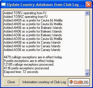
It will show you how many exceptions have been downloaded when it has completed (and the progress bar has moved across the top of your screen.)Once you have downloaded all the exceptions, click on "Updates" and then click on "Validate DXCC country codes from Clublog". This will open another window that allows you to choose what the process does with entries in your log. It would be a GREAT idea to backup your logbook, just in case you make changes that you do not want to make.
You can see the Options I picked in the photo on the upper Right. I was moving cautiously to make sure I didn't screw anything up. I chose NOT to change the DXCC country for any "Informational" entries in my log. These are entries that have an equal sign "=" after the callsign. They do not count for anything but are in my log for informational purposes. I also chose the "Manual" confirmation of changes. This caused a pop-up to appear for each potential change and I could manually "Approve" it or not. I also chose to NOT change any entry that had been approved by ARRL. And, I told Logger32 I was doing the full logbook and "promised" to recalculate my statistics later.
After the process completed, the box you see on the upper right was completed. It made 21 corrections to my log. This has not been a huge change in my log, but it definitely improved my statistics. For example, when I logged "N5AIU/R" (a Rover station I worked on 6-M), Logger32 gave me credit for working European Russia! This process removed that error.
Once you have done the entire logbook (and recalculated your statistics) you can set it to Automatically Update your log (Updates | Country database exceptions from Clublog | Enable auto updates.) The update will then automatically update daily.
This is another great feature of Logger32 - putting the power of Clublog to use to keep your logbook as accurate as possible. More instructions are in the Help file under "Clublog."
Posted by
W8TN
on
7/20/2014
0
comments
Labels: Logger32
Monday, April 7, 2014
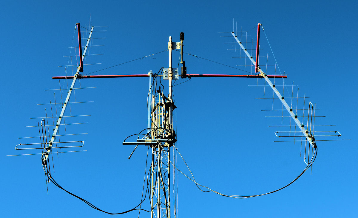
Antenna Question
I did not see it right away and had to go through several different thoughts and a couple of re-looks at the photo.
Click on the photo to see a larger image.
Posted by
W8TN
on
4/07/2014
2
comments
Labels: Humor
Monday, January 20, 2014
Amateur Equipment Inventory
The ARRL Contest Update for January 15, 2014, included a suggestion from the Mt. Airy VHF Radio Club's Cheese Bits newsletter that we, as hams, need to make an inventory of our equipment. The article is reprinted below with permission of ARRL. This is a useful idea not only for our spouse or whoever is charged with the duty of taking care of what we leave behind but can be beneficial for ourselves. It can remind you what you actually paid for an item or how long you've really owned it when you go to sell it.
We are all getting older, that's a given. And, for the most part, we
have a considerable inventory of ham radio related products. But, how
many of us actually have this inventory written down? I started doing
this many years ago in a Microsoft Word document but I got too detailed
on what I was trying to keep track of, and with my limited knowledge of
Microsoft Word, I had no way to sort it.
Even if you don't use Microsoft Excel to record this data, it can still
be very beneficial just to record the simplest record on paper or even
in Microsoft Word. Making this a New Year's resolution to simply "work"
on this project over the year is a good start. You don't have to
complete it by next Friday, just START on it TODAY!
Now go start this BASIC and SIMPLE inventory list TODAY! You can work on it as time is available but at least START it TODAY! I did! See above a Screen Shot of my beginning effort.
One Other Idea:
While I'm at it, you should also begin looking at Life and Death Planning (if you haven't already done so.) There is no guarantee for ANY of us as to how much time we have left so don't think that just because you are relatively young and healthy that this does not affect you. Below is a link to a good place to start. There is some very good information here as well as Checklists you can download and print to get yourself started. Plus, the website has an easy to remember name!
http://getyourshittogether.org/
========== Excerpt of ARRL Contest Update follows ==========
by John W3HMS
The Contest Update
wishes to thank the Pack Rats for their many contributions to this
newsletter and to VHF+ contesting over their long and storied history.
|
========== "Reprinted with the permission of the ARRL. © Copyright ARRL." ==========
Posted by
W8TN
on
1/20/2014
0
comments
Labels: Software, Tips & Techniques
Sunday, December 22, 2013
If a Tree Falls in the Woods, Will the Tower Still Stand?
Last night the weather forecast was: "While a few, scattered showers cannot be ruled
out throughout the evening and overnight...the main activity, in the
form of heavier rain, strong gusty winds and perhaps even a few
thunderstorms, won't near until 2-6 AM from west to east." Specific forecast predictions said the wind would hit Huntington between 3 and 4 a.m. and Charleston between 4 and 5 a.m. WELL - - - Just after 1 a.m. I was awakened by the house creaking and the sound of fast moving wind and rain. It lasted until about 2 a.m. which was a good deal longer than I had expected.
Yesterday was the first official day of winter and record temperatures were set in both Huntington and Charleston at 75°. The National Weather Service Area Forecast Discussion for Charleston at 12:30 a.m. on Sunday did not think the winds were going to be significant:
WINDS WILL BE GUSTY FROM THE SOUTH AND WEST THROUGH THE DAY TOMORROW. DID BUMP WINDS UP A BIT BASED ON THE NAM. NOT HIGH ENOUGH FOR WIND ADVISORY CRITERIA.
![]() |
| Base of the Two Trees |
![]() |
| Center Section of the Trees |
As you can see in the attached photos, the tree broke over about 5-1/2 to 6-feet above ground level. This had actually happened in a previous storm and the tree had been supported at about a 60° angle by adjacent trees.
Last night's storm finished the job of bringing it down. As you can see in the third photo below, the top part of the trees were resting on the guys for my tower. Click on any photo to see it larger.
Both of my go-to "Chain Saw Guys" were out of town so the job fell to me. I began cutting the two trees (which had grown up together) about 2-feet above the ground to get them low enough so that they could be cut off the guys. After I made my first wedge cut, I went back up the hill to get the gas can and bar oil for the chainsaw. At that point my neighbor (who owned the land where the tree was) came to help and he did the rest of the cutting while I did the pulling and such.
![]() |
| Top of Trees on Guy Wires |
Eventually we were able to free the guy wires but they are quite slack. I assume the tower has been pulled out of line and the guys may have been stretched due to the weight of the trees. I will assess that situation later and see what needs to be done. I'm just glad the tower is still standing!
I will need to go sight up the tower from the base and see how far it is out of line and see what can be done with the opposite guy wires to pull it back into line. Then, I need to see if there was any damage to the Phillystran from the trees. I saw nothing today but will want to check that just to be sure.
Could have been a WHOLE lot worse!
Posted by
W8TN
on
12/22/2013
0
comments
Labels: Tower
Friday, November 8, 2013
Recording QSO Audio on the K-3
An optional accessory for the Elecraft K-3 is the KDVR-3 Digital Voice Recorder. The main purpose of this device is to record your voice and then play it back by pushing a button - a Voice Keyer. However, it also has a feature where you can push a button (hold AF REC)and record the incoming rig audio. Hold AF REC again to stop recording. Push another button (hold AF PLAY) and it will play back that audio. Hold AF PLAY again to stop the playback. When in the playback mode, you can rotate the B VFO knob to select where in the 90 seconds you want to listen. A "*" indicates you are in the most recent recording segment.
The recording can be up to 90 seconds in length and when it completes 90 seconds it just starts recording over what it previously recorded - a 90 second loop of the received audio. Turn it on when you are about to call that rare DX and then turn it off after your QSO. You can then easily play it back and see if he really did get your call correct. You can also export the audio to your computer for archiving purposes (or to email to your buddies to brag about how well you copied the DX!)
Below is a link to an audio file (which I created using the KDVR-3) of my 80-M QSO with K9W on 8-Nov-2013 at 0800 GMT. I recorded this because I was using a 160-M Inverted-L with a single elevated radial as my 80-M transmit/receive antenna.
Click HERE to listen to the audio. Then use your BACK button to return to this page.
The trick to getting the audio out of the K-3 and into the computer is that you need to access the CONFIG : LIN OUT menu. When you first access that menu it will probably read "nor 010" or something like that. With that menu showing, you need to tap the "1" key. The menu will now show "=PHONES" and that means the K-3 will feed the same audio that goes to the headphones to the LINE OUT jack on the back of the K-3. This needs to be connected to your computer's LINE IN jack. After you have exported the K-3 recorded audio to the computer, access the CONFIG : LIN OUT menu again and tap the "1" key to remove the "=PHONES" feature. This puts the audio to your computer back to the normal level for PSK or other digital operation.
I use the program Audacity (which is a FREE program you can download from the Internet) to process and save my audio files. Just "Google" the word "Audacity" for more info. I run Audacity, start the Playback on the K-3, press the RECORD button in Audacity and then the STOP button when I reach the end of what I want to record. I can now trim the audio as necessary and perform other operations on the audio file to make it more legible before saving it.
Posted by
W8TN
on
11/08/2013
0
comments
Thursday, November 7, 2013
New 160-M Inverted-L Installed
Tim, K8RRT, volunteered to come with his bow and arrow and shoot a line over a likely tree. I got everything ready and when Tim arrived about 3 p.m. we measured out 130-feet of No. 14 solid for the vertical element and a second length for the single elevated radial.
Over the hill, Tim took only 2 shots to place his arrow right where he wanted it. We pulled back a small line and used that to pull the Dacron support line back over the tree. The spot where Tim placed the arrow is probably 80-feet above ground. Once the Dacron line was over the tree, I tied on the end of the vertical element and Tim pulled that over. At that point, Tim had to leave but all that was left was for me to connect the coax to the remote antenna switch and run out the elevated radial. It is no lower than 6 feet above ground and probably no higher than 10-feet. I finished about 5:40 p.m. (just after sunset.)
Once back in the shack I ran an SWR plot which you can see above. (Click on the photo for a larger image.) An SWR of 1.69:1 at 1.800 MHz drops down to 1.49:1 at 1.820 MHz. and pretty much stays there up to 1.900 MHz where it is 1.42:1
UPDATE: IT WORKS! I was able to work K9W on 80-M using this 160-M Inverted-L for a New One. Then, a little later, when they were calling CQ on 160-M, they sent "UP" and I sent my call ONE TIME and they came right back. I would say this puppy WORKS! Now, bring on T33A on Top-Band. I'm a "Happy Camper" to be back on Top-Band. Thanks, Tim!
Posted by
W8TN
on
11/07/2013
0
comments
New 40-M Wire Vertical Installed
I've been building a 40-M wire vertical here in the house
over the last few days and yesterday I installed it. It is a 33.3-foot
section of No. 14 stranded wire that stands off from the tower about
2-feet. You can see the 2x2 treated boards that hold the top and bottom
of the antenna in the photo on the right. (Click on any photo to see a larger image.) The
bottom of the vertical is about 27-feet above ground and the top is
about 60-feet. I have two elevated radials attached and both slope down
a little (they are not horizontal.) I wanted to get it as high up in
the air as possible because below 30-feet on the tower, everything to
the West is blocked by my hill.The photo on the left above shows the RF Choke which is about 21 feet of coax wound on a 6-inch form - about 12 turns. It is about 3-1/2 feet from the feedpoint of the antenna. It is marked "Coil" in the photo of the tower.
On the left is a plot of the SWR of this antenna. The antenna is pretty flat from about 7.1 to 7.2 but at a 1.6:1 SWR. It seems to be resonant about 7.125 MHz. I was shooting
for 7.025 MHz. and missed that by a good margin. I'm guessing that the
proximity of the tower is messing with the antenna both in the resonant
point and in the pattern. Still, it was easy to put this up
(relatively easy - I am WAY out of shape!)But, it was good enough for me to have a QSO with K9W this morning on 40-M SSB. The operator was Hal, W8HC, who was with me on Swains Island last year. That was HUGE to be able to work him on Wake Island - AND that was a New One for me on 40-M!. Obviously the antenna does get out as I only had to call twice to work him (at 43 minutes past my SR.)
Here are some spot checks of the SWR:
Posted by
W8TN
on
11/07/2013
0
comments
Sunday, November 3, 2013
CW Skimmer's View of the 5JØR Pileup on 17-M
At the left you can see a screen shot of CW Skimmer at K8RRT's QTH. He was decoding the pileup for 5JØR, San Andres & Providencia, who was transmitting on 18.074 MHz. It turns out that K9W, Wake Island, was also operational at the same time but the K9W station was not on 17-M at this particular time. K9W's stated transmit frequency on 17-M is 18.079 MHz. That would be square in the middle of the pileup on 5JØR! (Click on any picture to see a larger image.)On the right you can see the list of stations who were calling 5JØR, and who were being decoded by Tim's CW Skimmer program. Who knows how many others were calling that Tim was not able to copy? You can not see all the stations that CW Skimmer was decoding (see the extra yellow dots with no lines coming from them at the top of the image on the right) because Tim's monitor is not tall enough!
One interesting note is that while I was writing this Post, I was listening to 5JØR on 17-M. By my count, he made 20 QSO's between the times when he sent his own call. I looked at the clock when he made that second transmission of his callsign and then noted the time when he ID'd the next time. 12 minutes passed between those ID's! Considering the potential for confusion on which station you worked when there are multiple DX'peditions on the air at the same time (and similar transmit frequencies), it would be better if ALL DX'peditions gave their calls more often.
Posted by
W8TN
on
11/03/2013
0
comments
Sunday, September 22, 2013
Testing the Tin Can Stove
![]() |
| Owen Stirring |
![]() |
| Tin Can Stove in Operation |
Saturday night the boys came for a visit and brought the stove with them. We were having hot dogs with homemade chili (sauce) for dinner so they decided to heat the hot dog chili with their stove. It worked GREAT! The pan they had which fit exactly on top of the stove was a bit small but it worked fine. They just had to fill it three times to heat all the chili!
The stove consists of a Tuna Fish can with the tuna and the lid removed. Cardboard is cut and wound inside the can in a spiral and then filled with melted candle wax. The wicks from the melted candles are placed in the center of the cardboard spiral to allow easy lighting of the stove. A larger can has been cut (with the tin snips) to provide a place to slide the Tuna Fish can inside it. Vent holes are cut into the top of the larger can with a can opener. Then a piece of coat hanger is attached to the Tuna Fish can lid and the project is complete.
![]() |
| Grant Watching the Cook |
In the photo on the upper-right which shows Owen stirring the chili, you can see the Tuna Fish can lid that is attached to a coat hanger sitting on the paving stone. This is used to regulate the heat or to extinguish the flame. It worked quite well.
Dinner was an absolute success! And, after the stove was extinguished, there is still plenty of wax/cardboard "fuel" for a future "cook."
Posted by
W8TN
on
9/22/2013
0
comments
Saturday, August 3, 2013
K-3 Rotating Macros
With the Elecraft K-3 you have the ability to write macros and load them into the transceiver using the Download and Configuration Utility. "Macro" is short for "macroinstruction." It is a set of individual instructions grouped together into one large instruction that can tell a computer (or the K-3) to do several things. Once you load the macro to the K-3 you can then define a front panel button to execute the macro.
For some time I have been using two macros that I have configured to use the "PF1" and "PF2" buttons on the K-3's front panel. One of them would automatically set the "A" and "B" VFO's to the same
frequency, turn on the SHIFT, and move the "B" VFO up 2 kHz. That way,
if someone says "UP2" you can just hit 1 button and it will all be done
in a flash. I programmed the "PF1" button to shift UP 1 and "PF2" to shift UP 2 kHz. It worked great.
Recently I became aware of some "special" coding of these macros which allowed them to perform more than just the one single set of instructions. The "special" coding, in essence, would on the first push of the button execute the first part of the macro. Then, the remainder of the macro would re-program the button to perform another function on the second push.
I found many examples of macros in the K3 Configuration Utility Help file (Tab Pages | Command Tester/K3 Macros | Macro Buttons) as well as on KE7X's "Macro Repository" page HERE. In the above referenced Help item there is the following statement:
A command memory may include commands to assign macros to buttons. This results in one button executing different command macros on successive button presses.Think of it like a button that on the first push turns ON a lamp and on the next push, turns it OFF. The Help file then gives references to posts by KU4AF HERE and K1HTV HERE that give details on how to do this.
I took what I saw in the above references and adapted it to my use and for loading into the "PF1" and "PF2" buttons. The result was two separate "sets" of macros for the "PF1" and "PF2" buttons. I could also have programmed the M1-M4 memory buttons but I wanted to keep those for accessing the Voice and CW Memories.
What I decided to do was to set up one macro to put the radio into Split and after that was completed, re-program the same button to perform a "Cleanup" on the next button push. This "Cleanup" takes the radio out of Split mode and puts all the settings back to normal. The second button would be programmed to put the radio into SSB, CW, DATA A (PSK-31), and RTTY modes on each successive button push. To do this I had to set up 6 macros in the K-3 Configuration Utility. Two of the macros are programmed into the "PF1" button and 4 of them into the "PF2" button. Those 6 macros perform as follows - PF1 is now the Split ON/OFF button and PF2 is the Change Mode button. You can jump to the headings of "PF1 - - -"and "PF2 - - -" below in this Post to see each of those.
PF1 - - -
Once these macros have been loaded, the "PF1" button now performs like this,
Press PF1 - the K-3 goes into Split Mode
Press PF1 again - the K-3 goes back to normal
I have also changed what the K-3 does when it goes into Split Mode. Now when I press PF-1 the first time it turns on the SUB receiver, puts the VFO A information into VFO B, goes into Split Mode, moves VFO B up 3 kHz (so this button can be used for both CW and SSB splits - you just have to move the VFO B knob to where you need to be), turns off the RIT and XIT, and LOCKS the VFO A knob so you can't accidentally move it and lose the DX station. Pressing PF1 again will put everything back to normal. It is so COOL! You can move into Split Mode and back out with just a single button push plus you get all the other settings done at the same time with just one button! AWESOME!
The big changes here are that the PF1 button now automatically turns on the SUB Receiver and LOCKS the "A" VFO so you can't accidentally lose the DX station. A minor changes is that VFO B is now 3 kHz UP instead of just 1 or 2. That way, if it is a CW station saying UP1, you just have to tune VFO B down 2 kHz. If it is an SSB station saying UP5, then you just move the "B" VFO up 2 kHz. That way this Split button works for both CW and SSB. Heck, it even works for RTTY stations going split.
Below are the details of the changes to the PF1 button. First is a description of what is being done and then the Macro Label and actual Macro Commands are shown. Anyone can simply Copy and Paste these from this Post into their K-3 Configuration Utility so the setup of these features is FAST!
CW Split starting point (UP 3)
This is a split variation contributed by Dave, N1LQ. Dave chose a compromise between the +2 and +5 versions. A quick twist of VFO B puts Dave up or down depending on CW or SSB.
SB1; turns the sub receiver on
SWT13; taps A>B once to copy VFO A frequency to VFO B
SWT13; taps A>B again to copy all other settings to VFO B
FT1; enters Split mode.
UPB6; moves VFO B up 3 kHz
RT0; turns RIT off
XT0; turns XIT off
LK1; locks VFO A to prevent changes to the receiver listening to the DX station in the heat of the pileup
The following steps re-program the PF1 button to Macro #2
MN110; enters the CONFIG Menu
SWT12; taps the (2) button to choose Macro #2
SWH45; holds the PF1 button
SWT14; taps the Menu button
Macro Label #1 - Split+3
SB1;SWT13;SWT13;FT1;UPB6;RT0;
Cleanup
This is a "cleanup" macro contributed by Dave, N1LQ
SB0; turns the sub receiver off
FT0; turns split mode off
RT0; turns RIT off
XT0; turns XIT off
LN0; unlinks the VFOs
SQ000; turns squelch off
SWT13; taps A>B to copy VFO A frequency to VFO B
SWT13; taps A>B again to copy all other settings from VFO A to B
LK0; unlocks VFO A
The following steps re-program the PF1 button to Macro #1
MN110; enters the CONFIG Menu
SWT11; taps the (1) button to choose Macro #1
SWH45; holds the PF1 button
SWT14; taps the Menu button
Macro Label #2 - Cleanup
SB0;FT0;RT0;XT0;LN0;SQ000;
PF2 - - -
Press PF2 - the K-3 goes into USB Mode
Press PF2 again - the K-3 goes into CW Mode
Press PF2 again - the K-3 goes into DATA-A Mode (PSK-31 and other such modes)
Press PF2 again - the K-3 goes into RTTY Mode
Press PF2 again - the K-3 goes into USB Mode
. . . and so on
This looks like a lot of work but it should make things VERY simple to switch from USB to CW to PSK-31 to RTTY and back. But, remember - you do NOT need to use these buttons. If you find that doing it the old way works better for you, then leave this alone.
Now that I have programmed my K-3 to do these functions, I'll be checking it out to see if I need to fine tune any of the parameters. If anything needs to be changes, it's a simple thing to do.
Below is the detail for the four steps for the PF2 button:
Set SSB Parameters
MD2; selects USB mode
MN053; selects MIC SEL menu
DN; DN; moves the MIC SEL parameter down to Front Panel
UP; moves the MIC SEL up to Rear Panel (use this only if you are using the Rear MIC IN jack)
MG024; sets MIC Gain to "24" (insert appropriate numbers for your setup)
CP017; sets Speech Compression to "17" (insert appropriate numbers for your setup)
LK0; unlocks VFO A
BW0270; sets Bandwidth to 2.70 kHz.
The following steps re-program the PF2 button to Macro #4
MN110; enters the CONFIG Menu
SWT24; taps the (4) button to choose Macro #4
SWH47; holds the PF2 button
SWT14; taps the Menu button
Macro Label #3 - USB-PF2
MD2;MN053;DN;DN;UP;MG024;
Set CW Parameters
MD3; selects CWmode
LK0; unlocks VFO A
BW0040; sets Bandwidth to 400 Hz.
KS022; sets Keyer Speed to 22 WPM
The following steps re-program the PF2 button to Macro #5
MN110; enters the CONFIG Menu
SWT27; taps the (5) button to choose Macro #5
SWH47; holds the PF2 button
SWT14; taps the Menu button
Macro Label #4 - CW-PF2
MD3;LK0;BW0040;KS022;MN110;
Set DATA-A Parameters
MD6; selects DATA mode
DT0; selects Data-A sub-mode
MN053; selects MIC SEL menu
UP;UP; moves the MIC SEL parameter to Line In
BW0400; sets the Bandwidth to 4.0 kHz.
LK1; locks VFO A
The following steps re-program the PF2 button to Macro #6
MN110; enters the CONFIG Menu
SWT29; taps the (6) button to choose Macro #6
SWH47; holds the PF2 button
SWT14; taps the Menu button
Macro Label #5 - DTA-PF2
MD6;DT0;MN053;UP;UP;BW0400;
Set RTTY ParametersMD6; selects DATA mode
DT2; selects FSK D sub-mode
BW0050; sets the Bandwidth to 500 Hz.
LK0; unlocks VFO A
The following steps re-program the PF2 button to Macro #3
MN110; enters the CONFIG Menu
SWT13; taps the (3) button to choose Macro #3
SWH47; holds the PF2 button
SWT14; taps the Menu button
Macro Label #6 - RTT-PF2
MD6;DT2;BW0050;LK0;MN110;
The text labeled "Macro Label" goes into that field in the utility and the line underneath that is the actual macro text which goes into that field.
Macro Label #1 - Split+3
SB1;SWT13;SWT13;FT1;UPB6;RT0;XT0;LK1;MN110;SWT12;SWH45;SWT14;
Macro Label #2 - Cleanup
SB0;FT0;RT0;XT0;LN0;SQ000;
Macro Label #3 - USB-PF2
MD2;MN053;DN;DN;UP;MG024;
Macro Label #4 - CW-PF2
MD3;LK0;BW0040;KS022;MN110;
Macro Label #5 - DTA-PF2
MD6;DT0;MN053;UP;UP;BW0400;
Macro Label #6 - RTT-PF2
MD6;DT2;BW0050;LK0;MN110;
On the K-3 go to CONFIG:MACRO
Press "1"
HOLD the PF1 key until "PF1 SET" appears
Tap the "Menu" key
Then go to CONFIG:MACRO
Press "3"
HOLD the PF2 key until "PF2 SET" appears
Tap the "Menu" key
These steps assign the "Split" Macros to "PF1" and the "Mode Change" Macros to "PF2." If you want to assign these steps to other buttons, you need to change some of the settings (like the SWT or SWH commands that emulate button pushes) in the above coding.
If you have other things you want to put into macros or you want to put some of the above programming into other buttons, you can find a list of all the button commands in the "K-3 Programmers Reference" which is available on the Elecraft web site. I did not come up with these ideas, I just took what others have done and modified it to fit my particular use.
Posted by
W8TN
on
8/03/2013
2
comments
Friday, August 2, 2013
Logger32 Window for Control Of Alpha 87a
After doing the repair work on the Alpha 87a and hooking up the computer to talk to the amplifier, I remembered that my logging program, Logger32, has the ability to communicate to the Alpha 87a. So, I enabled that window and was immediately in control of the amp. As you can see in the photo, the amp is ON, in OPERATE, and HI POWER. The AlphaMax feature is OFF. The Fwd bar graph is indicating 1478 watts (according to the LP-100 wattmeter) and no reflected power is shown.
![]() |
| Logger32 Alpha 87a Control Window |
. . . when turned on causes Logger32 to automatically supply the active radio's active VFO frequency to the amplifier, which uses that information to change bands and select settings for its TUNE and LOAD capacitors from user- or factory-preset values stored in internal 87A memory for each of five band segments on each band covered by the amplifier. Although the 87A is capable of changing bands automatically on its own by sensing the frequency of RF drive power from the transceiver connected to it, quicker band- and segment-changes that put less stress on the internal PIN-diode QSK system of the 87A and eliminate the loss of the first dash or dots on cw (while the amplifier takes itself off-line and retunes in response to sensing the newly selected operating frequency from input RF) are made possible by having Logger32 supply the transceiver's new frequency across the serial interface.And, it works like a champ. Even with the 87a in STANDBY, when I change the frequency on the K-3, the Alpha tracks that change (courtesy of the "Auto Track Frequency" feature of Logger32) and the amp is immediately ready to transmit at full power. Awesome! It looks like I can click on a spot and hit transmit at full power without even the 1-1/2 second delay for the Alpha to tune to the new operating frequency or without the need to put any RF on the band to initiate tuning. But, the best thing is that it helps reduce the stress on the PIN diode QSK system in the amp.
One other big advantage of this window is that I can now see the status of the amplifier without turning around. At my station the amp is pretty much behind me and it can "Fault" and go offline so quietly that I do not know when I'm no longer transmitting at full power. Now I can see the power output and control the Standby/Operate switch right from the computer. Plus, I can shut the amp OFF and even turn it ON from the Logger32 Control Window. That's Just Sooo Cool!
Posted by
W8TN
on
8/02/2013
0
comments
Repairing the Alpha 87a - Round Two
I was floating along on a cloud after the successful repair of the Fault 1 problem (see Post below) but 12 days later, when attempting to power on the Alpha 87a, I got a "soft fault" designated as a No. 20 Fault Code. The manual describes this as "Filament current greater than 3.5 amp. Possible shorted filament." Bummer! Did that mean I was going to have to replace one or both of the 3CX800A7's in the amp? Eimac versions of those are now selling for $1,050 EACH but Alpha has just introduced their own line of tubes and I could get those for $400 each. Still, that's a BIG expense.
![]() |
| Underneath View of Alpha 87a Tube Compartment |
Now that I was ready to begin this new repair of the 87a I downloaded the PDF version of the manual from the Alpha web site to make it easier to read (on the computer instead of on paper.) I then pulled the 75 pound amp off the shelf after disconnecting the cables including the AC. Once again I needed to remove the "30" screws holding the cover to the chassis as well as four more screws that hold an access cover below the tube compartment. But, I've been down this road many times before so it's getting to be old hat.
The high voltage crowbar activates when the cover is removed and should eliminate any residual high voltage within the amplifier but I also short the high voltage to ground in the area of the tube plates or the plate RF choke with an insulated screwdriver as an extra precaution as described in the manual.
![]() |
| Large Red Connectors on Control Board Need to be Reseated |
Taking the photo at the upper left proved very useful to me. When I cleaned and attempted to re-install one of the 7 connectors in the tube compartment, I was having difficulty getting it to fit on the male pins. Then I noticed there were TWO male connectors on the board and I did not know which one was the correct one to accept the female connector. Looking at the photo clearly showed me there was an extra (unconnected) male connector. Also, and the reason I was having trouble plugging in the connector in the first place, the second connector is installed upside down (in relation to the correct one) and has more pins. The correct one has the two center pin holes plugged so it cannot be plugged into the wrong connector. Nice design by Alpha!
As an extra precaution, I put paper towels behind each connector while spraying it to make sure no "overspray" landed on any other components. Alpha did not mention this but I decided to take this step purely as a precaution.
Once all the connectors were re-installed, it was time to put the "34" screws back into the covers and reconnect all cables (after hoisting the 75-pound amp back onto the shelf.) I also took this opportunity to connect the Palstar AT-Auto tuner back into the station. That is another complex piece of equipment that required me to review the manual and make a few changes to the default settings for my particular station. One of those was to run the Keying Relay Input line for the Alpha 87a through the QRO Keyline circuit of the Palstar tuner. This will inhibit the keying of the Alpha 87a while the Palstar is tuning. Just one more piece of protection to keep me from hurting myself (or the Alpha) when (not IF) I make a mistake!
![]() |
| N8LP LP-100 Wattmenter Showing 1496 watts Output |
This entire operation took about 3 hours with about 2 of those spent on the actual dis-assembly/repair/reassembly of the Alpha 87a. I am REALLY thankful I did not have to purchase new tubes and the repair only cost $15 for the Deoxit plus a trip to Cross Lanes. I'd say that was more than reasonable!
One final thing I did was to connect the computer to the Alpha 87a and check the actual filament current. Alpha suggests you check it several times so I made 15 checks of the filament current over a 5-minute period and saw values ranging from 2.70 amps to 3.01 amps. Since the Fault Limit is 4.0 amps, I think the actual filament current is A-OK and the Fault 20 errors I received were erroneous and due completely to corrosion on one or more of the connectors in the amplifier. Case closed!
Posted by
W8TN
on
8/02/2013
1 comments
Sunday, July 21, 2013
Repairing the Alpha 87a Amplifier
Recently I mentioned on the WVDXA Reflector that I was running barefoot because my Alpha 87a was on the sick list. I was blown away by the many generous offers of help from WVDXA members. People offered to lend me amplifiers from all corners of the state. Those kind offers of help told me in no uncertain terms that the WVDXA as a whole sincerely wanted me to get out of the QRP category - and quickly! That motivated me to move the repair of my Alpha 87a to the top of my list.
![]() |
| Screws to Be Removed |
I am embarrassed to say that my amp went out more than 20 MONTHS ago! The issue was that as soon as the PTT line was keyed, the amp faulted and indicated the PIN back bias voltage was not at the minimum required level. This is known as a Fault 1 problem.
When it got sick, Charlie, N8RR, took the amp in for repair. He was able to reproduce the fault every time he keyed the amp. As soon as he started measuring the R Bias voltage, he noticed a loose connection which he tightened up. Once that was done, the Fault 1 problem never reappeared. He tried the amp out at his QTH and it made full power with no trouble. We both were relieved and thought Charlie had made a simple fix that solved the problem.
However, once the amp was back at my QTH, Mr. Murphy saw to it that the Fault 1 problem came back. I took apart the R Bias connection that Charlie had found to be loose, thoroughly cleaned it and "firmly" tightened it back up - but the Fault 1 issue was still there.
![]() |
| T/R Module under Screening |
Once the parts had been received, I looked carefully at the procedure to replace everything and was dismayed. 5 of the 6 parts went on the T/R Module PC board which is a real bear to remove. I have been in that compartment twice before over the 22+ years I have owned this amp and did not relish the job. 30 screws have to be removed just to get the cover off the amp. Then another 15 or 20 screws, nuts, flat washers, and lock washers need to be removed. Then, wires need to be unsoldered just to get at the PC board where the parts are to be replaced. Finally, two smaller boards have to be removed along with the T/R Module. I knew that I needed at least a couple of days where I would be doing NOTHING but working on this amp in order to have any chance of succeeding. If I started this project and then let it sit while I tackled something else, I would end up with a box of parts and pieces that I could never get back together. Plus, most of my free time in 2012 was taken up with the NH8S Swains Island DX'pedition.
I was not without an amp for the full 20 months as Charlie, N8RR, graciously lent me an AL-82 for about 6 months. He would have let me use it longer but I knew that I had to return it or I would not get off my duff and repair the 87a! Thanks Charlie!
![]() |
| T/R Module in Sub-Chassis |
I was finally successful in getting the board out of the sub-chassis without breaking anything and with only one small burn to a wire (made by a slip of the soldering iron.) Once it was free I took off a couple of hours to decompress!
When I came back to the project, it was not hard to remove the PIN diodes. However, I found that two of them had resistors soldered directly (and tightly) across them. I had not ordered replacement resistors so I needed to carefully unsolder those and salvage them for the new diodes. That was tedious but again I was successful. I was aided in removing the parts from the PC board by the fact that I had acquired (as a Christmas present several years ago) a neat desoldering tool. This is basically a soldering iron which is hollow and has a vacuum pump attached to it. Heat the joint with the iron and when the solder flows, hit the switch and suck the solder right out of the hole! Amazing!
![]() |
| Diode/Resistor String I Built |
Now I had to figure out how to remove the HV board. Luckily I found several photos on the Internet (HERE) posted by a guy who had done that so my worries over how to remove that board were moot. I pulled the HV board out in under 5 minutes (record time compared to the stress-filled adventure of taking out the T/R Module.) Replacing the diode was done in about 10 minutes and the HV board went back without a hitch.
I took the opportunity during the repair to remove what dust I could from inside the amp. In working on the T/R Module sub-chassis, I removed the 3CX800A7 tubes and gave them a thorough cleaning as well. I used compressed air liberally to blow out what dust I could and used anhydrous alcohol to clean most things. Once the repairs were completed, I spent about 15 minutes looking over everything to make sure I had not screwed up anything. During that check I did find one cable I had forgotten to re-attach! Whew! Dodged a bullet there.
![]() |
| Trying to Get T/R Module OUT |
So, Evelyn and I left to run some errands and ended up at Pizza Hut in Milton (since Teays Valley, Scott Depot and Hurricane were all without power.) We got home about 9:30 p.m. to find the power was back and after eating a bite I plugged in the amp and said a small prayer before pushing the switch.
Lo and behold the amp fired up, went through its boot up sequence and I marveled at how nice those LED's looked after the amp was dark for close to 2 years. When the time delay completed, and the amp switched to READY, there was a loud noise and the amp went dark. RATS! Murphy struck again.
![]() |
| T/R Module Removed |
Now to see if I had managed to fix the Fault 1 issue. I put the amp in operate and closed the PTT line with no drive applied. 20 months ago this would result in the amp Faulting with a Fault 1 code. But, this time, NO FAULT! Yippee!
Now to try the RF power test. I had been planning to test on 30-M but moved the rig to 17-M instead. That's where I made my first mistake. I had turned down the power level of the K-3 to 5 watts but that was on 30-M. On 17-M, the power level was still set to 109-watts! As soon as I hit the PTT, the amp faulted with a Fault 14 code (Excessive load reflected power or RF voltage.) Should have known that would happen. 65-watts of drive should give 1,500-watts out so 109-watts of drive was just a bit too much.
![]() |
| Technician At Work! |
This testing was a bit limited, I was not able to test power output much over 400-watts, but I'm cautiously optimistic that once I correct the SWR problem on the 17-M antenna, I will be back in business.
In the photo of me working on the amp, note that I have added an LED headlamp just above my Optivisor. That helps really put the light right on the spot where I need it! And, I have made no mention of the screws I took out that did not need to be removed, nor the 8 or 9 items that I dropped and had to search for on the floor. That's all forgotten now!
The next step is to hook up the Palstar AT-Auto tuner and get the 160-M Inverted-L back up. That should let me operate at or near full power on most bands like I have done before. This is, of course, a temporary situation. My efforts now need to be directed to fixing the SteppIR so I can again have a "real" antenna on every band.
So, I give a great big "THANK YOU" to the WVDXA members for spurring me to finish this project. The job was not as big as I had envisioned and I did not "kill" the amp while trying to repair it. But, don't ask me to dig back into that T/R Module sub-chassis anytime in the next DECADE!
Posted by
W8TN
on
7/21/2013
2
comments